Referring to the semiconductor processing tool of Problem 5.13, it is desired at some point in the manufacturing cycle to cool the chuck, which is made of aluminum alloy 2024. The proposed cooling scheme passes air at 20°C between the air-supply head and the chuck surface. (a) If the chuck is initially at a uniform temperature of l00°C, calculate the time required for its lower surface to reach 25°C, assuming a uniform convection coefficient of 50 W / m 2 ⋅ K at the head—chuck interface. (b) Generate a plot of the time-to-cool as a function of the convection coefficient for the range 10 ≤ h ≤ 2000 W / m 2 ⋅ K . If the lower limit represents a free convection condition without any head present, comment on the effectiveness of the head design as a method for cooling the chuck.
Referring to the semiconductor processing tool of Problem 5.13, it is desired at some point in the manufacturing cycle to cool the chuck, which is made of aluminum alloy 2024. The proposed cooling scheme passes air at 20°C between the air-supply head and the chuck surface. (a) If the chuck is initially at a uniform temperature of l00°C, calculate the time required for its lower surface to reach 25°C, assuming a uniform convection coefficient of 50 W / m 2 ⋅ K at the head—chuck interface. (b) Generate a plot of the time-to-cool as a function of the convection coefficient for the range 10 ≤ h ≤ 2000 W / m 2 ⋅ K . If the lower limit represents a free convection condition without any head present, comment on the effectiveness of the head design as a method for cooling the chuck.
Solution Summary: The author explains how the thermal insulation system can maintain oxygen losses below 1kg/day.
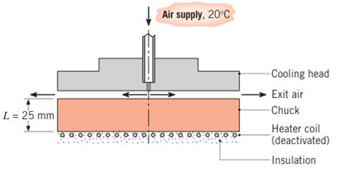
Referring to the semiconductor processing tool of Problem 5.13, it is desired at some point in the manufacturing cycle to cool the chuck, which is made of aluminum alloy 2024. The proposed cooling scheme passes air at 20°C between the air-supply head and the chuck surface.
(a) If the chuck is initially at a uniform temperature of l00°C, calculate the time required for its lower surface to reach 25°C, assuming a uniform convection coefficient of
50
W
/
m
2
⋅
K
at the head—chuck interface.
(b) Generate a plot of the time-to-cool as a function of the convection coefficient for the range
10
≤
h
≤
2000
W
/
m
2
⋅
K
. If the lower limit represents a free convection condition without any head present, comment on the effectiveness of the head design as a method for cooling the chuck.
my ID# 016948724. Please solve this problem step by step
My ID# 016948724 please find the forces for Fx=0: fy=0: fz=0: please help me to solve this problem step by step
My ID# 016948724 please solve the proble step by step find the forces fx=o: fy=0; fz=0; and find shear moment and the bending moment diagran please draw the diagram for the shear and bending moment
Need a deep-dive on the concept behind this application? Look no further. Learn more about this topic, mechanical-engineering and related others by exploring similar questions and additional content below.


 Principles of Heat Transfer (Activate Learning wi...Mechanical EngineeringISBN:9781305387102Author:Kreith, Frank; Manglik, Raj M.Publisher:Cengage Learning