Concept explainers
For the case of double-circuit, bundle-conductor lines, the same method indicated in Problem 4.27 applies with r' replaced by the bundle’s GMR in the calculation of the overall GMR.
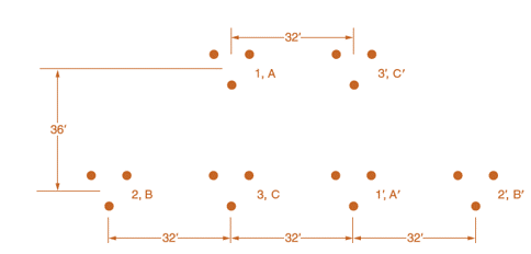
Now consider a double-circuit configuration shown in Figure 4.36 that belongs to a 500-kV, three-phase line with bundle conductors of three subconductors at 21 in. spacing. The GMR of each subconductor is given to be 0.0485 ft.
Determine the inductive reactance of the line in ohms per mile per phase. You may use
Trending nowThis is a popular solution!
Chapter 4 Solutions
Power System Analysis and Design (MindTap Course List)
- Figure 4.34 shows double-circuit conductors' relative positions in segment I of transposition of a completely transposed three-phase overhead transmission line. The inductance is given by L=2107lnGMDGMRH/m/phase Where GMD=(DABeqDBCeqDACeq)1/3 With mean distances defined by equivalent spacings DABeq=(D12D12D12D12)1/4DBCeq=(D23D23D23D13)1/4DACeq=(D13D13D13)1/4 And GMR=[ (GMR)A(GMR)B(GMR)C ]1/3 with phase GMRs defined by (GMR)A=[ rD11 ]1/2;(GMR)B=[ rD22 ]1/2;(GMR)C=[ rD33 ]1/2 and r is the GMR of phase conductors. Now consider a 345-kV, three-phase, double-circuit line with phase-conductors GMR of 0.0588 ft and the horizontal conductor configuration shown in Figure 4.35. Determine the inductance per meter per phase in Henries (H). Calculate the inductance of just one circuit and then divide by 2 to obtain the inductance of the double circuit.arrow_forwardThe capacitance of a single-circuit, three-phase transposed line with the configuration shown in Figure 4.38, including ground effect, and with conductors not equilaterally spaced is given by C20lnDeqrlnHmH8 F/m line-to-neutral where Deq=D12D23D133=GMD r= conductors outside radiusHm=(H12H23H13)1/3HS=(H1H2H3)1/3 Now consider Figure 4.39 in which the configuration of a three-phase, single circuit, 345-kV line with conductors having an outside diameter of 1.065 in. is shown. Determine the capacitance to neutral in F/m, including the ground effect. Next, neglecting the effect of ground, see how the value changes.arrow_forwardConsider the 500 kV, three phase bundled conductor line as shown in the figure below. Find the line to neutral capacitance. 0.5 m 30 mm (0) (O to Ine 15 m 15 marrow_forward
- (a) A three phase transposed transmission tower comprises of three-bundled conductor and double-circuit configured in vertical position as shown in Figure 2. Each sub-conductor in each circuit and each phase is an ACSR type, size 477,000 cmil and stranding 26/7. Given the GMR of each sub-conductor is 0.8809 cm and diameter is 2.1793 cm, analyze: i. Inductance in mH/km ii. Capacitance in µF/km 0.75m 7.5m b' 4m 4m 45cm Figure 2arrow_forwardThere are conductor x (number of conductors = 3) and conductor y (number ofconductors = 2’) for a 50 Hz single phase two-conductor line as shown in Figure below. The linelength is 20 miles. a. Calculate GMRx, GMRy and GMD b. Calculate Lx, Ly and total L in H/m. c. Calculate XL in /m per circuit.arrow_forwardPlease answer both.. I will ratearrow_forward
- Question number 6 decent handwriting pls both the parts!arrow_forwardFor the system in Figure 4 with given generation and load dispatch determine the voltages after two itterations of Gauss-Seidel method. Assume the initial voltage to be 1.01 at angle of 0◦ pu at bus 1, 1.015 at angle of 0◦ pu at bus 2, and 1.0 at angle of 0◦ pu at bus 3. All line impedances are in per unit on a common base, and charging is neglected. Take base power of 100 MVA.arrow_forwardYou are given that the system shown in Figure 4.25 has a 110/220 kV autotransformer. The positive- and zero-sequence impedances in ohms or percent are as shown in the figure, the zero-sequence impedances being in parentheses. Assume that the low- voltage system is solidly grounded. For a phase-a-to-ground fault at the midpoint of the transmission line, calculate the transformer current In in the neutral and the phase a currents Ia and I'a on the high and low sides of the transformer. If the source on the low-voltage side is to be grounded through a reactance, determine the value of the grounding reactance for which the transformer neutral current becomes zero. As the grounding reactance changes around this value, the direction of the neutral current will reverse, and will affect the polarizing capability of the neutral current for ground faults on the high side. Can faults on the low-voltage side ever cause the neutral current to reverse?arrow_forward
- 4.8. A three-phase transposed line is composed of one ACSR 159,000 cmil, 54/19 Lapwing conductor per phase with flat horizontal spacing of 8 meters as shown in Figure 37. The GMR of each conductor is 1.515 cm. (a) Determine the inductance per phase per kilometer of the line. (b) This line is to be replaced by a two-conductor bundle with 8-m spacing mea- sured from the center of the bundles as shown in Figure 38. The spacing between the conductors in the bundle is 40 cm. If the line inductance per phase is to be 77 percent of the inductance in part (a), what would be the GM R of each new conductor in the bundle? a D12 = 8 m D23 = 8 m %3D %3D -D13 = 16 m- FIGURE 37 Conductor layout for Problem 4.8 (a).arrow_forwardQ2. Figure Q2 shows the single-line diagram. The scheduled loads at buses 2 and 3 are as marked on the diagram. Line impedances are marked in per unit on 100 MVA base and the line charging susceptances are neglected. a) Using Gauss-Seidel Method, determine the phasor values of the voltage at load bus 2 and 3 according to second iteration results. b) Find slack bus real and reactive power according to second iteration results. c) Determine line flows and line losses according to second iteration results. d) Construct a power flow according to second iteration results. Slack Bus = 1.04.20° 0.025+j0.045 0.015+j0.035 0.012+j0,03 3 |2 134.8 MW 251.9 MW 42.5 MVAR 108.6 MVARarrow_forwardA 60 Hz, three-phase, transposed transmission line, is designed with three bobolink conductors per phase, in horizontal arrangement as shown in the figure below. Distance between consecutive phases is D = 6.2 m and distance among bundle conductors is h =0.5m. Each conductor has a radius of 18 mm and a GMR of 14.39mm. The per phase resistance is 1.677x10⁻⁵ 2/m. r= 18 mm GMR= 14.39 mm a b h D D The per phase shunt admittance assuming zero conductance in µO/km is: О a., 5.4347 O b. j5.3316 О с /4.2266 O d. j4.0973 O e. 59630.2922 + j10.9770arrow_forward
- Power System Analysis and Design (MindTap Course ...Electrical EngineeringISBN:9781305632134Author:J. Duncan Glover, Thomas Overbye, Mulukutla S. SarmaPublisher:Cengage Learning