
Mechanics of Materials (10th Edition)
10th Edition
ISBN: 9780134319650
Author: Russell C. Hibbeler
Publisher: PEARSON
expand_more
expand_more
format_list_bulleted
Concept explainers
Videos
Textbook Question
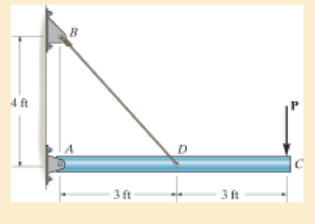
Chapter 3.4, Problem 3.15P
The rigid pipe is supported by a pin at A and an A-36 guy wire BD. If the wire has a diameter of 0.25 in., determine the load P if the end C is displaced 0.075 in. downward.
Expert Solution & Answer
Want to see the full answer?
Check out a sample textbook solution
Students have asked these similar questions
Problem 3: The inertia matrix can be written in dyadic form which is particularly useful
when inertia information is required in various vector bases. On the next page is a right
rectangular pyramid of total mass m. Note the location of point Q.
(a) Determine the inertia dyadic for the pyramid P, relative to point Q, i.e., 7%, for unit
vectors ₁₁, 2, 3.
Can you solve for v? Also, what is A x u
The external loads on the element shown below at the free end are F = 1.75 kN, P = 9.0
kN, and T = 72 Nm.
The tube's outer diameter is 50 mm and the inner diameter is 45 mm.
Given: A(the cross-sectional area) is 3.73 cm², Moment inertial I is 10.55 cm4, and J
polar moment inertial is 21.1 cm4.
Determine the following.
(1) The critical element(s) of the bar.
(2) Show the state of stress on a stress element for each critical element.
-120 mm-
F
Chapter 3 Solutions
Mechanics of Materials (10th Edition)
Ch. 3.4 - Define a homogeneous material.Ch. 3.4 - Indicate the points on the stress-strain diagram...Ch. 3.4 - Define the modulus of elasticity E.Ch. 3.4 - At room temperature, mild steel is a ductile...Ch. 3.4 - Engineering stress and strain are calculated using...Ch. 3.4 - As the temperature increases the modulus of...Ch. 3.4 - A 100-mm-long rod has a diameter of 15 mm. If an...Ch. 3.4 - A bar has a length of 8 in. and cross-sectional...Ch. 3.4 - A 10-mm-diameter rod has a modulus of elasticity...Ch. 3.4 - The material for the 50-mm-long specimen has the...
Ch. 3.4 - The material for the 50-mm-long specimen has the...Ch. 3.4 - If the elongation of wire BC is 0.2 mm after the...Ch. 3.4 - A tension test was performed on a steel specimen...Ch. 3.4 - Data taken from a stress-strain test for a ceramic...Ch. 3.4 - Data taken from a stress-strain test for a ceramic...Ch. 3.4 - The stress-strain diagram for a steel alloy having...Ch. 3.4 - The stress-strain diagram for a steel alloy having...Ch. 3.4 - The stress-strain diagram for a steel alloy having...Ch. 3.4 - The rigid beam is supported by a pin at C and an...Ch. 3.4 - The rigid beam is supported by a pin at C and an...Ch. 3.4 - Acetal plastic has a stress-strain diagram as...Ch. 3.4 - The stress-strain diagram for an aluminum alloy...Ch. 3.4 - The stress-strain diagram for an aluminum alloy...Ch. 3.4 - The stress-strain diagram for an aluminum alloy...Ch. 3.4 - A bar having a length of 5 in. and cross-sectional...Ch. 3.4 - The rigid pipe is supported by a pin at A and an...Ch. 3.4 - The rigid pipe is supported by a pin at A and an...Ch. 3.4 - Direct tension indicators are sometimes used...Ch. 3.4 - The rigid beam is supported by a pin at C and an...Ch. 3.4 - The rigid beam is supported by a pin at C and an...Ch. 3.4 - The stress-strain diagram for a bone is shown, and...Ch. 3.4 - The stress-strain diagram for a bone is shown and...Ch. 3.4 - The two bars are made of a material that has the...Ch. 3.4 - The two bars are made of a material that has the...Ch. 3.4 - The pole is supported by a pin at C and an A-36...Ch. 3.4 - The bar DA is rigid and is originally held in the...Ch. 3.7 - A 100-mm-long rod has a diameter of 15 mm. If an...Ch. 3.7 - A solid circular rod that is 600 mm long and 20 mm...Ch. 3.7 - A 20-mm-wide block is firmly bonded to rigid...Ch. 3.7 - A 20-mm-wide block is bonded to rigid plates at...Ch. 3.7 - The acrylic plastic rod is 200 mm long and 15 mm...Ch. 3.7 - The plug has a diameter of 30 mm and fits within a...Ch. 3.7 - The elastic portion of the stress-strain diagram...Ch. 3.7 - The elastic portion of the stress-strain diagram...Ch. 3.7 - The brake pads for a bicycle tire are made of...Ch. 3.7 - The lap joint is connected together using a 1.25...Ch. 3.7 - The lap joint is connected together using a 1.25...Ch. 3.7 - The rubber block is subjected to an elongation of...Ch. 3.7 - The shear stress-strain diagram for an alloy is...Ch. 3.7 - A shear spring is made from two blocks of rubber,...Ch. 3 - The elastic portion of the tension stress-strain...Ch. 3 - The elastic portion of the tension stress-strain...Ch. 3 - The rigid beam rests in the horizontal position on...Ch. 3 - The wires each have a diameter of 12 in., length...Ch. 3 - The wires each have a diameter of 12 in., length...Ch. 3 - diameter steel bolts. If the clamping force in...Ch. 3 - The stress-strain diagram for polyethylene, which...Ch. 3 - The pipe with two rigid caps attached to its ends...Ch. 3 - The 8-mm-diameter bolt is made of an aluminum...Ch. 3 - An acetal polymer block is fixed to the rigid...
Additional Engineering Textbook Solutions
Find more solutions based on key concepts
A nozzle at A discharges water with an initial velocity of 36 ft/s at an angle with the horizontal. Determine ...
Vector Mechanics For Engineers
The solid steel shaft AC has a diameter of 25 mm and is supported by smooth bearings at D and E. It is coupled ...
Mechanics of Materials (10th Edition)
Why is the study of database technology important?
Database Concepts (8th Edition)
Assume a telephone signal travels through a cable at two-thirds the speed of light. How long does it take the s...
Electric Circuits. (11th Edition)
17–1C A high-speed aircraft is cruising in still air. How does the temperature of air at the nose of the aircra...
Thermodynamics: An Engineering Approach
Knowledge Booster


Learn more about
Need a deep-dive on the concept behind this application? Look no further. Learn more about this topic, mechanical-engineering and related others by exploring similar questions and additional content below.Similar questions
- A crate weighs 530 lb and is hung by three ropes attached to a steel ring at A such that the top surface is parallel to the xy plane. Point A is located at a height of h = 42 in above the top of the crate directly over the geometric center of the top surface. Use the dimensions given in the table below to determine the tension in each of the three ropes. 2013 Michael Swanbom ↑ Z C BY NC SA b x B у D Values for dimensions on the figure are given in the following table. Note the figure may not be to scale. Variable Value a 30 in b 43 in с 4.5 in The tension in rope AB is lb The tension in rope AC is lb The tension in rope AD is lbarrow_forwardThe airplane weighs 144100 lbs and flies at constant speed and trajectory given by 0 on the figure. The plane experiences a drag force of 73620 lbs. a.) If = 11.3°, determine the thrust and lift forces required to maintain this speed and trajectory. b.) Next consider the case where is unknown, but it is known that the lift force is equal to 7.8 times the quantity (Fthrust Fdrag). Compute the resulting trajectory angle - and the lift force in this case. Use the same values for the weight and drag forces as you used for part a. Уллу Fdrag 10. Ө Fthrust cc 10 2013 Michael Swanbom BY NC SA Flift Fweight The lift force acts in the y' direction. The weight acts in the negative y direction. The thrust and drag forces act in the positive and negative x' directions respectively. Part (a) The thrust force is equal to lbs. The lift force is equal to Part (b) The trajectory angle is equal to deg. The lift force is equal to lbs. lbs.arrow_forwardThe hoist consists of a single rope and an arrangement of frictionless pulleys as shown. If the angle 0 = 59°, determine the force that must be applied to the rope, Frope, to lift a load of 4.4 kN. The three-pulley and hook assembly at the center of the system has a mass of 22.5 kg with a center of mass that lies on the line of action of the force applied to the hook. e ΘΕ B CC 10 BY NC SA 2013 Michael Swanbom Fhook Note the figure may not be to scale. Frope = KN HO Fropearrow_forward
- Determine the tension developed in cables AB and AC and the force developed along strut AD for equilibrium of the 400-lb crate. x. 5.5 ft C 2 ft Z 2 ft D 6 ft B 4 ft A 2.5 ftarrow_forwardA block of mass m hangs from the end of bar AB that is 7.2 meters long and connected to the wall in the xz plane. The bar is supported at A by a ball joint such that it carries only a compressive force along its axis. The bar is supported at end B by cables BD and BC that connect to the xz plane at points C and D respectively with coordinates given in the figure. Cable BD is elastic and can be modeled as a linear spring with a spring constant k = 400 N/m and unstretched length of 6.34 meters. Determine the mass m, the compressive force in beam AB and the tension force in cable BC. Z D (c, 0, d) C (a, 0, b), A e B y f m BY NC SA x 2016 Eric Davishahl Values for dimensions on the figure are given in the following table. Note the figure may not be to scale. Variable Value a 8.1 m b 3.3 m C 2.7 m d 3.9 m e 2 m f 5.4 m The mass of the block is The compressive force in bar AB is The tension in cable S is N. kg.arrow_forwardTwo squirrels are sitting on the rope as shown. The squirrel at A has a weight of 1.2 lb. The squirrel at B found less food this season and has a weight of 0.8 lb. The angles 0 and > are equal to 50° and 60° respectively. Determine the tension force in each of the rope segments (T₁ in segment, T₂ in segment Я, and T3 in segment DD) as well as the angle a in degrees. Ө A α B Note the figure may not be to scale. T₁ = lb lb T2 T3 = = lb απ deg A BY NC SA 2013 Michael Swanbomarrow_forward
- Each cord can sustain a maximum tension of 500 N. Determine the largest mass of pipe that can be supported. B 60° A E Harrow_forward2. Link BD consists of a single bar 1 in. wide and 0.5 in. thick. Knowing that each pin has a in. diameter, determine (a) the maximum value of the normal stress in link BD and the bearing stress in link BD if 0 = 0, (b) the maximum value of the normal stress in link BD if 0 = 90. -6 in.- 12 in. 30° D 4 kipsarrow_forwardIn the image is a right rectangular pyramid of total mass m. Note the location of point Q. Determine the inertia dyadic for the pyramid P, relative to point Q for e hat unit vectors.arrow_forward
arrow_back_ios
SEE MORE QUESTIONS
arrow_forward_ios
Recommended textbooks for you
 Elements Of ElectromagneticsMechanical EngineeringISBN:9780190698614Author:Sadiku, Matthew N. O.Publisher:Oxford University Press
 Mechanics of Materials (10th Edition)Mechanical EngineeringISBN:9780134319650Author:Russell C. HibbelerPublisher:PEARSON
 Thermodynamics: An Engineering ApproachMechanical EngineeringISBN:9781259822674Author:Yunus A. Cengel Dr., Michael A. BolesPublisher:McGraw-Hill Education
 Control Systems EngineeringMechanical EngineeringISBN:9781118170519Author:Norman S. NisePublisher:WILEY
 Mechanics of Materials (MindTap Course List)Mechanical EngineeringISBN:9781337093347Author:Barry J. Goodno, James M. GerePublisher:Cengage Learning
 Engineering Mechanics: StaticsMechanical EngineeringISBN:9781118807330Author:James L. Meriam, L. G. Kraige, J. N. BoltonPublisher:WILEY
Elements Of Electromagnetics
Mechanical Engineering
ISBN:9780190698614
Author:Sadiku, Matthew N. O.
Publisher:Oxford University Press
Mechanics of Materials (10th Edition)
Mechanical Engineering
ISBN:9780134319650
Author:Russell C. Hibbeler
Publisher:PEARSON
Thermodynamics: An Engineering Approach
Mechanical Engineering
ISBN:9781259822674
Author:Yunus A. Cengel Dr., Michael A. Boles
Publisher:McGraw-Hill Education
Control Systems Engineering
Mechanical Engineering
ISBN:9781118170519
Author:Norman S. Nise
Publisher:WILEY
Mechanics of Materials (MindTap Course List)
Mechanical Engineering
ISBN:9781337093347
Author:Barry J. Goodno, James M. Gere
Publisher:Cengage Learning
Engineering Mechanics: Statics
Mechanical Engineering
ISBN:9781118807330
Author:James L. Meriam, L. G. Kraige, J. N. Bolton
Publisher:WILEY
EVERYTHING on Axial Loading Normal Stress in 10 MINUTES - Mechanics of Materials; Author: Less Boring Lectures;https://www.youtube.com/watch?v=jQ-fNqZWrNg;License: Standard YouTube License, CC-BY