
Mechanics of Materials (10th Edition)
10th Edition
ISBN: 9780134319650
Author: Russell C. Hibbeler
Publisher: PEARSON
expand_more
expand_more
format_list_bulleted
Concept explainers
Videos
Textbook Question
Chapter 3.4, Problem 3.3P
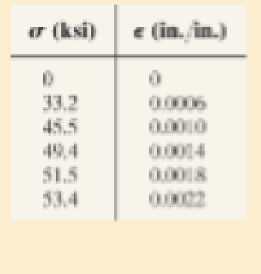
Data taken from a stress-strain test for a ceramic are given in the table. The curve is linear between the origin and the first point. Plot the diagram, and determine approximately the modulus of toughness. The fracture stress is σf = 53.4 ksi.
Expert Solution & Answer
Want to see the full answer?
Check out a sample textbook solution
Students have asked these similar questions
got wrong answers help please
A crate weighs 530 lb and is hung by three ropes attached to
a steel ring at A such that the top surface is parallel to the
xy plane. Point A is located at a height of h = 42 in above
the top of the crate directly over the geometric center of the
top surface. Use the dimensions given in the table below to
determine the tension in each of the three ropes.
2013 Michael Swanbom
cc00
BY NC SA
↑ Z
C
b
B
У
a
D
Values for dimensions on the figure are given in the following
table. Note the figure may not be to scale.
Variable Value
a
30 in
b
43 in
4.5 in
The tension in rope AB is 383
x lb
The tension in rope AC is 156
x lb
The tension in rope AD is 156
x lb
A block of mass m hangs from the end of bar AB that is 7.2
meters long and connected to the wall in the xz plane. The
bar is supported at A by a ball joint such that it carries only a
compressive force along its axis. The bar is supported at end
B by cables BD and BC that connect to the xz plane at
points C and D respectively with coordinates given in the
figure. Cable BD is elastic and can be modeled as a linear
spring with a spring constant k = 400 N/m and unstretched
length of 6.34 meters.
Determine the mass m, the compressive force in beam AB
and the tension force in cable BC.
Z
C
D
(c, 0, d)
(a, 0, b)
A
B
y
f
m
cc 10
BY
NC SA
2016 Eric Davishahl
x
Values for dimensions on the figure are given in the following
table. Note the figure may not be to scale.
Variable Value
a
8.1 m
b
3.3 m
с
2.7 m
d
3.9 m
e
2 m
f
5.4 m
The mass of the block is 68.8
The compressive force in bar AB is
364
× kg.
× N.
The tension in cable BC is 393
× N.
Chapter 3 Solutions
Mechanics of Materials (10th Edition)
Ch. 3.4 - Define a homogeneous material.Ch. 3.4 - Indicate the points on the stress-strain diagram...Ch. 3.4 - Define the modulus of elasticity E.Ch. 3.4 - At room temperature, mild steel is a ductile...Ch. 3.4 - Engineering stress and strain are calculated using...Ch. 3.4 - As the temperature increases the modulus of...Ch. 3.4 - A 100-mm-long rod has a diameter of 15 mm. If an...Ch. 3.4 - A bar has a length of 8 in. and cross-sectional...Ch. 3.4 - A 10-mm-diameter rod has a modulus of elasticity...Ch. 3.4 - The material for the 50-mm-long specimen has the...
Ch. 3.4 - The material for the 50-mm-long specimen has the...Ch. 3.4 - If the elongation of wire BC is 0.2 mm after the...Ch. 3.4 - A tension test was performed on a steel specimen...Ch. 3.4 - Data taken from a stress-strain test for a ceramic...Ch. 3.4 - Data taken from a stress-strain test for a ceramic...Ch. 3.4 - The stress-strain diagram for a steel alloy having...Ch. 3.4 - The stress-strain diagram for a steel alloy having...Ch. 3.4 - The stress-strain diagram for a steel alloy having...Ch. 3.4 - The rigid beam is supported by a pin at C and an...Ch. 3.4 - The rigid beam is supported by a pin at C and an...Ch. 3.4 - Acetal plastic has a stress-strain diagram as...Ch. 3.4 - The stress-strain diagram for an aluminum alloy...Ch. 3.4 - The stress-strain diagram for an aluminum alloy...Ch. 3.4 - The stress-strain diagram for an aluminum alloy...Ch. 3.4 - A bar having a length of 5 in. and cross-sectional...Ch. 3.4 - The rigid pipe is supported by a pin at A and an...Ch. 3.4 - The rigid pipe is supported by a pin at A and an...Ch. 3.4 - Direct tension indicators are sometimes used...Ch. 3.4 - The rigid beam is supported by a pin at C and an...Ch. 3.4 - The rigid beam is supported by a pin at C and an...Ch. 3.4 - The stress-strain diagram for a bone is shown, and...Ch. 3.4 - The stress-strain diagram for a bone is shown and...Ch. 3.4 - The two bars are made of a material that has the...Ch. 3.4 - The two bars are made of a material that has the...Ch. 3.4 - The pole is supported by a pin at C and an A-36...Ch. 3.4 - The bar DA is rigid and is originally held in the...Ch. 3.7 - A 100-mm-long rod has a diameter of 15 mm. If an...Ch. 3.7 - A solid circular rod that is 600 mm long and 20 mm...Ch. 3.7 - A 20-mm-wide block is firmly bonded to rigid...Ch. 3.7 - A 20-mm-wide block is bonded to rigid plates at...Ch. 3.7 - The acrylic plastic rod is 200 mm long and 15 mm...Ch. 3.7 - The plug has a diameter of 30 mm and fits within a...Ch. 3.7 - The elastic portion of the stress-strain diagram...Ch. 3.7 - The elastic portion of the stress-strain diagram...Ch. 3.7 - The brake pads for a bicycle tire are made of...Ch. 3.7 - The lap joint is connected together using a 1.25...Ch. 3.7 - The lap joint is connected together using a 1.25...Ch. 3.7 - The rubber block is subjected to an elongation of...Ch. 3.7 - The shear stress-strain diagram for an alloy is...Ch. 3.7 - A shear spring is made from two blocks of rubber,...Ch. 3 - The elastic portion of the tension stress-strain...Ch. 3 - The elastic portion of the tension stress-strain...Ch. 3 - The rigid beam rests in the horizontal position on...Ch. 3 - The wires each have a diameter of 12 in., length...Ch. 3 - The wires each have a diameter of 12 in., length...Ch. 3 - diameter steel bolts. If the clamping force in...Ch. 3 - The stress-strain diagram for polyethylene, which...Ch. 3 - The pipe with two rigid caps attached to its ends...Ch. 3 - The 8-mm-diameter bolt is made of an aluminum...Ch. 3 - An acetal polymer block is fixed to the rigid...
Knowledge Booster


Learn more about
Need a deep-dive on the concept behind this application? Look no further. Learn more about this topic, mechanical-engineering and related others by exploring similar questions and additional content below.Similar questions
- The airplane weighs 144100 lbs and flies at constant speed and trajectory given by 0 on the figure. The plane experiences a drag force of 73620 lbs. 0 a.) If 11.3°, determine the thrust and lift forces = required to maintain this speed and trajectory. b.) Next consider the case where is unknown, but it is known that the lift force is equal to 7.8 times the quantity (Fthrust Fdrag). Compute the resulting trajectory angle and the lift force in this case. Use the same values for the weight and drag forces as you used for part a. 20. YAAY' Farag Ө Fthrust CC + BY NC SA 2013 Michael Swanbom Flift Fweight The lift force acts in the y' direction. The weight acts in the negative y direction. The thrust and drag forces act in the positive and negative x' directions respectively. Part (a) The thrust force is equal to 101,855 ☑ lbs. The lift force is equal to 141,282 ☑ lbs. Part (b) The trajectory angle 0 is equal to 7.31 ✓ deg. The lift force is equal to 143,005 ☑ lbs.arrow_forwardsimply supported beam has a concentrated moment M, applied at the left support and a concentrated force F applied at the free end of the overhang on the right. Using superposition, determine the deflection equations in regions AB and BC.arrow_forwardwhat is heat exchanger, what are formulas, and their importance, define the diagram, and give me a script on how to explain the design of heat exchanger, and how did values end up in that number. based on standards . what is dshellarrow_forward
- FIGURE P1.37 1.38 WP As shown in Figure P1.38, an inclined manometer is used to measure the pressure of the gas within the reservoir, (a) Using data on the figure, determine the gas pressure, in lbf/in.² (b) Express the pressure as a gage or a vacuum pressure, as appropriate, in lbf/in.² (c) What advantage does an inclined manometer have over the U-tube manometer shown in Figure 1.7? Patm = 14.7 lbf/in.² L I C i Gas a Oil (p = 54.2 lb/ft³) 140° 8=32.2 ft/s² 15 in.arrow_forwardwhat is an low pressure Heater, what are formulas, and their importance, define the diagram, and give me a script on how to explain the design of an air preheater, and how did values end up in that number. based on standardsarrow_forwardwhat is an air preheater, what are formulas, and their importance, define the diagram, and give me a script on how to explain the design of an air preheater, and how did values end up in that number. based on standardsarrow_forward
- Qf, Qa,Qm, Qcon,Qfg, Qbd, Qref,Qloss ( meaning, formula, percentage, and importance of higher value na qf, qa etc)arrow_forwardThe beam is supported by a fixed support at point C and a roller at point A. It also has an internal hinge at point B. The beam supports a point load at point D, a moment at point A and a distributed load on segment BC. a. calculate the support reactions at points A and C b. calculate the internal resultant loadings (N, V, M) at points E and F, which lies in the middle between points A and D P = 4 kip Ma = 5 kip-ft w1 = 3 kip/ft and w2 = 4 kip/ft a = 3 ftarrow_forwardFrom the image of the pyramid, I want to find what s1 hat, s2 hat, and s3 hat are. I think s3 hat is just equal to e3 hat right? What about the others?arrow_forward
arrow_back_ios
SEE MORE QUESTIONS
arrow_forward_ios
Recommended textbooks for you
 Elements Of ElectromagneticsMechanical EngineeringISBN:9780190698614Author:Sadiku, Matthew N. O.Publisher:Oxford University Press
 Mechanics of Materials (10th Edition)Mechanical EngineeringISBN:9780134319650Author:Russell C. HibbelerPublisher:PEARSON
 Thermodynamics: An Engineering ApproachMechanical EngineeringISBN:9781259822674Author:Yunus A. Cengel Dr., Michael A. BolesPublisher:McGraw-Hill Education
 Control Systems EngineeringMechanical EngineeringISBN:9781118170519Author:Norman S. NisePublisher:WILEY
 Mechanics of Materials (MindTap Course List)Mechanical EngineeringISBN:9781337093347Author:Barry J. Goodno, James M. GerePublisher:Cengage Learning
 Engineering Mechanics: StaticsMechanical EngineeringISBN:9781118807330Author:James L. Meriam, L. G. Kraige, J. N. BoltonPublisher:WILEY
Elements Of Electromagnetics
Mechanical Engineering
ISBN:9780190698614
Author:Sadiku, Matthew N. O.
Publisher:Oxford University Press
Mechanics of Materials (10th Edition)
Mechanical Engineering
ISBN:9780134319650
Author:Russell C. Hibbeler
Publisher:PEARSON
Thermodynamics: An Engineering Approach
Mechanical Engineering
ISBN:9781259822674
Author:Yunus A. Cengel Dr., Michael A. Boles
Publisher:McGraw-Hill Education
Control Systems Engineering
Mechanical Engineering
ISBN:9781118170519
Author:Norman S. Nise
Publisher:WILEY
Mechanics of Materials (MindTap Course List)
Mechanical Engineering
ISBN:9781337093347
Author:Barry J. Goodno, James M. Gere
Publisher:Cengage Learning
Engineering Mechanics: Statics
Mechanical Engineering
ISBN:9781118807330
Author:James L. Meriam, L. G. Kraige, J. N. Bolton
Publisher:WILEY
Strain energy and strain energy density introduced; Author: Engineer4Free;https://www.youtube.com/watch?v=m14sqLGg4BQ;License: Standard youtube license