
Mechanics of Materials (10th Edition)
10th Edition
ISBN: 9780134319650
Author: Russell C. Hibbeler
Publisher: PEARSON
expand_more
expand_more
format_list_bulleted
Videos
Textbook Question
Chapter 3.7, Problem 3.27P
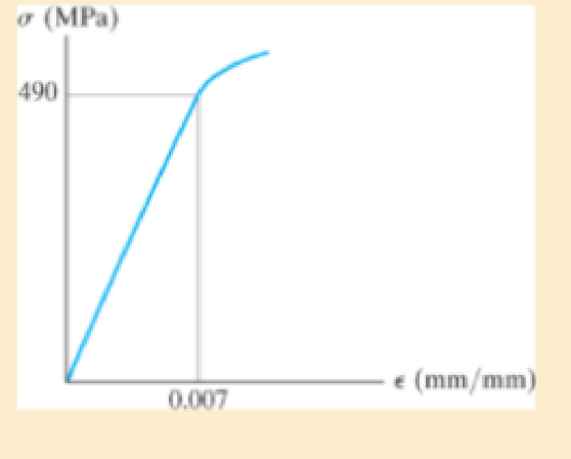
The elastic portion of the stress-strain diagram for an aluminum alloy is shown in the figure. The specimen from which it was obtained has an original diameter of 12.7 mm and a gage length of 50.8 mm. When the applied load on the specimen is 50 kN, the diameter is 12.67494 mm. Determine Poisson’s ratio for the material.
Expert Solution & Answer
Want to see the full answer?
Check out a sample textbook solution
Students have asked these similar questions
Correct answer is written below. Detailed and complete solution with fbd only. I will upvote, thank you. Expert solution pls
Correct answer is written below. Detailed and complete solution with fbd only. I will upvote, thank you.
Correct answer is written below. Detailed and complete solution with fbd only. I will upvote, thank you.
Chapter 3 Solutions
Mechanics of Materials (10th Edition)
Ch. 3.4 - Define a homogeneous material.Ch. 3.4 - Indicate the points on the stress-strain diagram...Ch. 3.4 - Define the modulus of elasticity E.Ch. 3.4 - At room temperature, mild steel is a ductile...Ch. 3.4 - Engineering stress and strain are calculated using...Ch. 3.4 - As the temperature increases the modulus of...Ch. 3.4 - A 100-mm-long rod has a diameter of 15 mm. If an...Ch. 3.4 - A bar has a length of 8 in. and cross-sectional...Ch. 3.4 - A 10-mm-diameter rod has a modulus of elasticity...Ch. 3.4 - The material for the 50-mm-long specimen has the...
Ch. 3.4 - The material for the 50-mm-long specimen has the...Ch. 3.4 - If the elongation of wire BC is 0.2 mm after the...Ch. 3.4 - A tension test was performed on a steel specimen...Ch. 3.4 - Data taken from a stress-strain test for a ceramic...Ch. 3.4 - Data taken from a stress-strain test for a ceramic...Ch. 3.4 - The stress-strain diagram for a steel alloy having...Ch. 3.4 - The stress-strain diagram for a steel alloy having...Ch. 3.4 - The stress-strain diagram for a steel alloy having...Ch. 3.4 - The rigid beam is supported by a pin at C and an...Ch. 3.4 - The rigid beam is supported by a pin at C and an...Ch. 3.4 - Acetal plastic has a stress-strain diagram as...Ch. 3.4 - The stress-strain diagram for an aluminum alloy...Ch. 3.4 - The stress-strain diagram for an aluminum alloy...Ch. 3.4 - The stress-strain diagram for an aluminum alloy...Ch. 3.4 - A bar having a length of 5 in. and cross-sectional...Ch. 3.4 - The rigid pipe is supported by a pin at A and an...Ch. 3.4 - The rigid pipe is supported by a pin at A and an...Ch. 3.4 - Direct tension indicators are sometimes used...Ch. 3.4 - The rigid beam is supported by a pin at C and an...Ch. 3.4 - The rigid beam is supported by a pin at C and an...Ch. 3.4 - The stress-strain diagram for a bone is shown, and...Ch. 3.4 - The stress-strain diagram for a bone is shown and...Ch. 3.4 - The two bars are made of a material that has the...Ch. 3.4 - The two bars are made of a material that has the...Ch. 3.4 - The pole is supported by a pin at C and an A-36...Ch. 3.4 - The bar DA is rigid and is originally held in the...Ch. 3.7 - A 100-mm-long rod has a diameter of 15 mm. If an...Ch. 3.7 - A solid circular rod that is 600 mm long and 20 mm...Ch. 3.7 - A 20-mm-wide block is firmly bonded to rigid...Ch. 3.7 - A 20-mm-wide block is bonded to rigid plates at...Ch. 3.7 - The acrylic plastic rod is 200 mm long and 15 mm...Ch. 3.7 - The plug has a diameter of 30 mm and fits within a...Ch. 3.7 - The elastic portion of the stress-strain diagram...Ch. 3.7 - The elastic portion of the stress-strain diagram...Ch. 3.7 - The brake pads for a bicycle tire are made of...Ch. 3.7 - The lap joint is connected together using a 1.25...Ch. 3.7 - The lap joint is connected together using a 1.25...Ch. 3.7 - The rubber block is subjected to an elongation of...Ch. 3.7 - The shear stress-strain diagram for an alloy is...Ch. 3.7 - A shear spring is made from two blocks of rubber,...Ch. 3 - The elastic portion of the tension stress-strain...Ch. 3 - The elastic portion of the tension stress-strain...Ch. 3 - The rigid beam rests in the horizontal position on...Ch. 3 - The wires each have a diameter of 12 in., length...Ch. 3 - The wires each have a diameter of 12 in., length...Ch. 3 - diameter steel bolts. If the clamping force in...Ch. 3 - The stress-strain diagram for polyethylene, which...Ch. 3 - The pipe with two rigid caps attached to its ends...Ch. 3 - The 8-mm-diameter bolt is made of an aluminum...Ch. 3 - An acetal polymer block is fixed to the rigid...
Knowledge Booster


Learn more about
Need a deep-dive on the concept behind this application? Look no further. Learn more about this topic, mechanical-engineering and related others by exploring similar questions and additional content below.Similar questions
- Correct answer is written below. Detailed and complete solution only with fbd. I will upvote, thank you.arrow_forwardCorrect answer is written below. Detailed and complete solution only. I will upvote, thank you.arrow_forwardCorrect answer is written below. Detailed and complete solution with fbd only. I will upvote, thank you.arrow_forward
- Correct answer is written below. Detailed and complete solution only. I will upvote, thank you.arrow_forwardCorrect answer is written below. Detailed and complete solution with fbd only. I will upvote, thank you.arrow_forwardCorrect answer is written below. Detailed and complete solution only. I will upvote, thank you.arrow_forward
- Correct answer is written below. Detailed and complete solution only. I will upvote, thank you.arrow_forwardCorrect answer is written below. Detailed and complete solution only. I will upvote, thank you.arrow_forwardCorrect answer is written below. Detailed and complete solution with fbd only. I will upvote, thank you. Prefferably handwritten solution pleasearrow_forward
- Correct answer is written below. Detailed and complete solution with fbd only. I will upvote, thank you. Prefferably handwritten solution pleasearrow_forwardCorrect answer is written below. Detailed and complete solution only. I will upvote, thank you.arrow_forwardCorrect answer is written below. Detailed and complete solution with fbd only. I will upvote, thank you. Prefferably handwritten solution pleasearrow_forward
arrow_back_ios
SEE MORE QUESTIONS
arrow_forward_ios
Recommended textbooks for you
 Elements Of ElectromagneticsMechanical EngineeringISBN:9780190698614Author:Sadiku, Matthew N. O.Publisher:Oxford University Press
 Mechanics of Materials (10th Edition)Mechanical EngineeringISBN:9780134319650Author:Russell C. HibbelerPublisher:PEARSON
 Thermodynamics: An Engineering ApproachMechanical EngineeringISBN:9781259822674Author:Yunus A. Cengel Dr., Michael A. BolesPublisher:McGraw-Hill Education
 Control Systems EngineeringMechanical EngineeringISBN:9781118170519Author:Norman S. NisePublisher:WILEY
 Mechanics of Materials (MindTap Course List)Mechanical EngineeringISBN:9781337093347Author:Barry J. Goodno, James M. GerePublisher:Cengage Learning
 Engineering Mechanics: StaticsMechanical EngineeringISBN:9781118807330Author:James L. Meriam, L. G. Kraige, J. N. BoltonPublisher:WILEY
Elements Of Electromagnetics
Mechanical Engineering
ISBN:9780190698614
Author:Sadiku, Matthew N. O.
Publisher:Oxford University Press
Mechanics of Materials (10th Edition)
Mechanical Engineering
ISBN:9780134319650
Author:Russell C. Hibbeler
Publisher:PEARSON
Thermodynamics: An Engineering Approach
Mechanical Engineering
ISBN:9781259822674
Author:Yunus A. Cengel Dr., Michael A. Boles
Publisher:McGraw-Hill Education
Control Systems Engineering
Mechanical Engineering
ISBN:9781118170519
Author:Norman S. Nise
Publisher:WILEY
Mechanics of Materials (MindTap Course List)
Mechanical Engineering
ISBN:9781337093347
Author:Barry J. Goodno, James M. Gere
Publisher:Cengage Learning
Engineering Mechanics: Statics
Mechanical Engineering
ISBN:9781118807330
Author:James L. Meriam, L. G. Kraige, J. N. Bolton
Publisher:WILEY
An Introduction to Stress and Strain; Author: The Efficient Engineer;https://www.youtube.com/watch?v=aQf6Q8t1FQE;License: Standard YouTube License, CC-BY