
Concept explainers
Videos
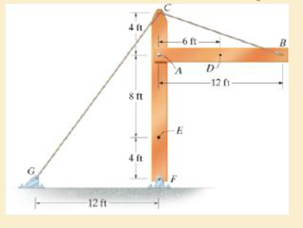
The beam AB is pin supported at A and supported by a cable BC. A separate cable CG is used to hold up the frame. If AB weighs 120 lb/ft and the column FC has a weight of 180 lb/ft, determine the resultant internal loadings acting on cross sections located at points D and E.
Answer to Problem 1.1RP
The resultant internal loadings at cross section at D are
The resultant internal loadings at cross section at E are
Explanation of Solution
Given information:
The beam AB is pin supported at A and supported by a cable BC.
The weight of the beam AB is
The weight of the column FC is
Calculation:
Find the loading at the center of the beam AB
Substitute
Convert the unit from lb to kip.
Sketch the Free Body Diagram of the beam AB shown in Figure 1.
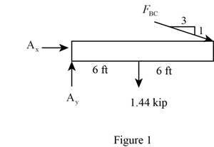
Refer to Figure 1.
Find the angle of cable BC to the horizontal
Find the tension in cable BC as shown below.
Take moment about A is Equal to zero.
Find the support reaction at A as shown below.
Apply the Equations of Equilibrium as shown below.
Summation of forces along horizontal direction is Equal to zero.
Summation of forces along vertical direction is Equal to zero.
Find the loading at the center of the beam AD
Substitute
Convert the unit from lb to kip.
Sketch the Free Body Diagram of the section for point D as shown in Figure 2.
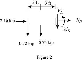
Refer to Figure 2.
Find the internal loadings as shown below.
Apply the Equations of Equilibrium as shown below.
Summation of forces along horizontal direction is Equal to zero.
Summation of forces along vertical direction is Equal to zero.
Take moment about D is Equal to zero.
Hence, the resultant internal loadings at cross section at D are
Find the loading at the center of the column FC
Substitute
Convert the unit from lb to kip.
Sketch the Free Body Diagram of the beam FC shown in Figure 3.
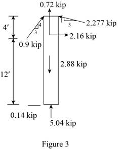
Refer to Figure 3.
Find the angle of cable CG to the horizontal.
Find the tension in cable CG as shown below.
Summation of forces along horizontal direction is Equal to zero.
Find the loading at the center of the column FE
Substitute
Convert the unit from lb to kip.
Sketch the Free Body Diagram of the section for point E as shown in Figure 4.
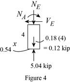
Refer to Figure 4.
Find the internal loadings as shown below.
Apply the Equations of Equilibrium as shown below.
Summation of forces along horizontal direction is Equal to zero.
Summation of forces along vertical direction is Equal to zero.
Take moment about E is Equal to zero.
Therefore, the resultant internal loadings at cross section at E are
Want to see more full solutions like this?
Chapter 1 Solutions
Mechanics of Materials (10th Edition)
Additional Engineering Textbook Solutions
Starting Out with Java: From Control Structures through Objects (7th Edition) (What's New in Computer Science)
Degarmo's Materials And Processes In Manufacturing
Starting Out with C++: Early Objects (9th Edition)
Computer Science: An Overview (13th Edition) (What's New in Computer Science)
Introduction To Programming Using Visual Basic (11th Edition)
Starting Out with Python (4th Edition)


- (Read image)arrow_forward(Read Image)arrow_forwardM16x2 grade 8.8 bolts No. 25 C1- Q.2. The figure is a cross section of a grade 25 cast-iron pressure vessel. A total of N, M16x2.0 grade 8.8 bolts are to be used to resist a separating force of 160 kN. (a) Determine ks, km, and C. (b) Find the number of bolts required for a load factor of 2 where the bolts may be reused when the joint 19 mm is taken apart. (c) with the number of bolts obtained in (b), determine the realized load factor for overload, the yielding factor of safety, and the separation factor of safety. 19 mmarrow_forward
- Problem4. The thin uniform disk of mass m = 1-kg and radius R = 0.1m spins about the bent shaft OG with the angular speed w2 = 20 rad/s. At the same time, the shaft rotates about the z-axis with the angular speed 001 = 10 rad/s. The angle between the bent portion of the shaft and the z-axis is ẞ = 35°. The mass of the shaft is negligible compared to the mass of the disk. a. Find the angular momentum of the disk with respect to point G, based on the axis orientation as shown. Include an MVD in your solution. b. Find the angular momentum of the disk with respect to point O, based on the axis orientation as shown. (Note: O is NOT the center of fixed-point rotation.) c. Find the kinetic energy of the assembly. z R R 002 2R x Answer: H = -0.046ĵ-0.040 kg-m²/sec Ho=-0.146-0.015 kg-m²/sec T 0.518 N-m =arrow_forwardProblem 3. The assembly shown consists of a solid sphere of mass m and the uniform slender rod of the same mass, both of which are welded to the shaft. The assembly is rotating with angular velocity w at a particular moment. Find the angular momentum with respect to point O, in terms of the axes shown. Answer: Ñ。 = ½mc²wcosßsinßĵ + (}{mr²w + 2mb²w + ½ mc²wcos²ß) k 3 m r b 2 C لا marrow_forwardOnly question 2arrow_forward
- Only question 1arrow_forwardOnly question 3arrow_forwardI have Euler parameters that describe the orientation of N relative to Q, e = -0.7071*n3, e4 = 0.7071. I have Euler parameters that describe the orientation of U relative to N, e = -1/sqrt(3)*n1, e4 = sqrt(2/3). After using euler parameter rule of successive rotations, I get euler parameters that describe the orientation of U relative to Q, e = -0.4082*n1 - 0.4082*n2 - 0.5774*n3. I need euler parameters that describe the orientation of U relative to Q in vector basis of q instead of n. How do I get that?arrow_forward
- Describe at least 4 processes in engineering where control charts are (or should be) appliedarrow_forwardDescribe at least two (2) processes where control charts are (or should be) applied.arrow_forwardProblem 3: A cube-shaped spacecraft is in a circular Earth orbit. Let N (n,) be inertial and the spacecraft is denoted S (ŝ₁). The spacecraft is described such that ¯½º = J ŝ₁ŝ₁ + J ŝ₂§₂ + J §¸Ŝ3 Location of the spacecraft in the orbit is determined by the orbit-fixed unit vectors ê, that are oriented by the angle (Qt), where is a constant angular rate. 52 €3 3> 2t 55 Λ Из At the instant when Qt = 90°, the spacecraft S is oriented relative to the orbit such that 8₁ = 0° Space-three 1-2-3 angles 0₂ = 60° and ES = $₂ rad/s 0₁ = 135° (a) At this instant, determine the direction cosine matrix that describes the orientation of the spacecraft with respect to the inertial frame N.arrow_forward
 Elements Of ElectromagneticsMechanical EngineeringISBN:9780190698614Author:Sadiku, Matthew N. O.Publisher:Oxford University Press
 Mechanics of Materials (10th Edition)Mechanical EngineeringISBN:9780134319650Author:Russell C. HibbelerPublisher:PEARSON
 Thermodynamics: An Engineering ApproachMechanical EngineeringISBN:9781259822674Author:Yunus A. Cengel Dr., Michael A. BolesPublisher:McGraw-Hill Education
 Control Systems EngineeringMechanical EngineeringISBN:9781118170519Author:Norman S. NisePublisher:WILEY
 Mechanics of Materials (MindTap Course List)Mechanical EngineeringISBN:9781337093347Author:Barry J. Goodno, James M. GerePublisher:Cengage Learning
 Engineering Mechanics: StaticsMechanical EngineeringISBN:9781118807330Author:James L. Meriam, L. G. Kraige, J. N. BoltonPublisher:WILEY