
Mechanics of Materials (10th Edition)
10th Edition
ISBN: 9780134319650
Author: Russell C. Hibbeler
Publisher: PEARSON
expand_more
expand_more
format_list_bulleted
Concept explainers
Videos
Textbook Question
Chapter 1.7, Problem 1.93P
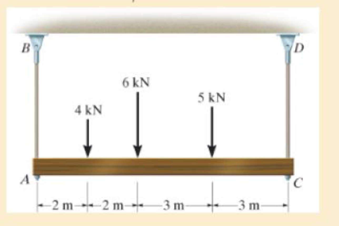
The rods AB and CD are made of steel. Determine their smallest diameter so that they can support the dead loads shown. The beam is assumed to be pin connected at A and C. Use the LRFD method, where the resistance factor for steel in tension is ϕ = 0.9. and the dead load factor is γD = 1.4. The failure stress is σfail = 345 MPa.
Expert Solution & Answer
Want to see the full answer?
Check out a sample textbook solution
Students have asked these similar questions
Need help!
need help understanding?
%94 KB/S
Find : 1. dynamic load on each bearing due to the out-of-balance couple; and 2. kinetic energy of
the complete assembly.
[Ans. 6.12 kg: 8.7 N-m]
L
2.
3.
4.
5.
1.
2.
5.
DO YOU KNOW?
Why is balancing of rotating parts necessary for high speed engines?
Explain clearly the terms "static balancing' and 'dynamic balancing'. State the necessary conditions
to achieve them.
Discuss how a single revolving mass is balanced by two masses revolving in different planes.
Chapter 21: Balancing of Rotating Masses .857
Explain the method of balancing of different masses revolving in the same plane.
How the different masses rotating in different planes are balanced?
OBJECTIVE TYPE QUESTIONS
The balancing of rotating and reciprocating parts of an engine is necessary when it runs at
(a) slow speed
(b) medium speed (c) high speed
A disturbing mass, attached to a rotating shaft may be balanced by a single mass m, attached in
the same plane of rotation as that of my such that
(a)
(b) F
For static…
Chapter 1 Solutions
Mechanics of Materials (10th Edition)
Ch. 1.2 - In each case, explain how to find the resultant...Ch. 1.2 - Determine the resultant internal normal force,...Ch. 1.2 - Determine the resultant internal normal force,...Ch. 1.2 - Determine the resultant internal normal force,...Ch. 1.2 - Determine the resultant internal normal force,...Ch. 1.2 - Determine the resultant internal normal force,...Ch. 1.2 - Determine the resultant internal normal force,...Ch. 1.2 - The shaft is supported by a smooth thrust bearing...Ch. 1.2 - Determine the resultant internal normal and shear...Ch. 1.2 - Determine the resultant internal loadings acting...
Ch. 1.2 - The shaft is supported by a smooth thrust bearing...Ch. 1.2 - Determine the resultant internal loadings acting...Ch. 1.2 - Determine the resultant internal loadings on the...Ch. 1.2 - Determine the resultant internal loadings at cross...Ch. 1.2 - The beam supports the distributed load shown....Ch. 1.2 - The beam supports the distributed load shown....Ch. 1.2 - The boom DF of the jib crane and the column DE...Ch. 1.2 - Determine the resultant internal loadings acting...Ch. 1.2 - Determine the resultant internal loadings acting...Ch. 1.2 - The blade of the hacksaw is subjected to a...Ch. 1.2 - The blade of the hacksaw is subjected to a...Ch. 1.2 - The beam supports the triangular distributed load...Ch. 1.2 - The beam supports the distributed load shown....Ch. 1.2 - The shaft is supported at its ends by two bearings...Ch. 1.2 - The shaft is supported at its ends by two bearings...Ch. 1.2 - The hand crank that is used in a press has the...Ch. 1.2 - Determine the resultant internal loadings acting...Ch. 1.2 - Determine the resultant internal loadings acting...Ch. 1.2 - The metal stud punch is subjected to a force of...Ch. 1.2 - Determine the resultant internal loadings acting...Ch. 1.2 - Determine the resultant internal loadings acting...Ch. 1.2 - Determine the resultant internal loadings acting...Ch. 1.2 - Determine the resultant internal loadings acting...Ch. 1.2 - The pipe has a mass of 12 kg/m. If it is fixed to...Ch. 1.2 - If the drill bit jams when the brace is subjected...Ch. 1.2 - The curved rod AD of radius r has a weight per...Ch. 1.2 - A differential element taken from a curved bar is...Ch. 1.5 - In each case, determine the largest internal shear...Ch. 1.5 - Determine the largest internal normal force in the...Ch. 1.5 - Determine the internal normal force at section A...Ch. 1.5 - The lever is held to the fixed shaft using the pin...Ch. 1.5 - The single-V butt joint transmits the force of 5...Ch. 1.5 - The uniform beam is supported by two rods AB and...Ch. 1.5 - Determine the average normal stress on the cross...Ch. 1.5 - Determine the average normal stress on the cross...Ch. 1.5 - If the 600-kN force acts through the centroid of...Ch. 1.5 - Determine the average normal stress at points A,...Ch. 1.5 - Determine the average normal stress in rod AB if...Ch. 1.5 - The supporting wheel on a scaffold is held in...Ch. 1.5 - Determine the largest intensity w of the uniform...Ch. 1.5 - The bar has a cross-sectional area A and is...Ch. 1.5 - The small block has a thickness of 0.5 in. If the...Ch. 1.5 - If the material fails when the average normal...Ch. 1.5 - If the block is subjected to a centrally applied...Ch. 1.5 - The plate has a width of 0.5 m. If the stress...Ch. 1.5 - The board is subjected to a tensile force of 200...Ch. 1.5 - The boom has a uniform weight of 600 lb and is...Ch. 1.5 - Determine the average normal stress in each of the...Ch. 1.5 - If the average normal stress in each of the...Ch. 1.5 - Determine the maximum average shear stress in pin...Ch. 1.5 - If P=5 kN, determine the average shear stress in...Ch. 1.5 - Determine the maximum magnitude P of the loads the...Ch. 1.5 - The column is made of concrete having a density of...Ch. 1.5 - The beam is supported by two rods AB and CD that...Ch. 1.5 - The beam is supported by two rods AB and CD that...Ch. 1.5 - If P = 15 kN, determine the average shear stress...Ch. 1.5 - The railcar docklight is supported by the...Ch. 1.5 - The plastic block is subjected to an axial...Ch. 1.5 - The two steel members are joined together using a...Ch. 1.5 - The bar has a cross-sectional area of 400(106) m2....Ch. 1.5 - The bar has a cross-sectional area of 400(106) m2....Ch. 1.5 - The two members used in the construction of an...Ch. 1.5 - The 2-Mg concrete pipe has a center of mass at...Ch. 1.5 - The 2-Mg concrete pipe has a center of mass at...Ch. 1.5 - The pier is made of material having a specific...Ch. 1.5 - Rods AB and BC have diameters of 4 mm and 6 mm,...Ch. 1.5 - The uniform bar, having a cross-sectional area of...Ch. 1.5 - The bar has a cross-sectional area of 400(106) m2....Ch. 1.5 - The bar has a cross-sectional area of 400(106) m2....Ch. 1.5 - The prismatic bar has a cross-sectional area A. If...Ch. 1.5 - The prismatic bar has a cross-sectional area A. If...Ch. 1.5 - The bars of the truss each have a cross-sectional...Ch. 1.5 - The bars of the truss each have a cross-sectional...Ch. 1.5 - Determine the largest load P that can be applied...Ch. 1.5 - Determine the greatest constant angular velocity ...Ch. 1.5 - The radius of the pedestal is defined by r =...Ch. 1.7 - Rods AC and BC are used to suspend the 200-kg...Ch. 1.7 - If it is subjected to double shear, determine the...Ch. 1.7 - Determine the maximum average shear stress...Ch. 1.7 - If each of the three nails has a diameter of 4 mm...Ch. 1.7 - The strut is glued to the horizontal member at...Ch. 1.7 - Determine the maximum average shear stress...Ch. 1.7 - If the eyebolt is made of a material having a...Ch. 1.7 - If the bar assembly is made of a material having a...Ch. 1.7 - Determine the maximum force P that can be applied...Ch. 1.7 - The pin is made of a material having a failure...Ch. 1.7 - If the bolt head and the supporting bracket are...Ch. 1.7 - Six nails are used to hold the hanger at A against...Ch. 1.7 - If A and B are both made of wood and are 38 in....Ch. 1.7 - Prob. 1.70PCh. 1.7 - The connection is made using a bolt and nut and...Ch. 1.7 - The tension member is fastened together using two...Ch. 1.7 - The steel swivel bushing in the elevator control...Ch. 1.7 - The spring mechanism is used as a shock absorber...Ch. 1.7 - Determine the size of square bearing plates A and...Ch. 1.7 - Determine the maximum load P that can be applied...Ch. 1.7 - Determine the required diameter of the pins at A...Ch. 1.7 - If the allowable tensile stress for wires AB and...Ch. 1.7 - If the allowable tensile stress for wires AB and...Ch. 1.7 - The cotter is used to hold the two rods together....Ch. 1.7 - Determine the required diameter of the pins at A...Ch. 1.7 - The steel pipe is supported on the circular base...Ch. 1.7 - The boom is supported by the winch cable that has...Ch. 1.7 - The boom is supported by the winch cable that has...Ch. 1.7 - The assembly consists of three disks A, B, and C...Ch. 1.7 - The two aluminum rods support the vertical force...Ch. 1.7 - The two aluminum rods AB and AC have diameters of...Ch. 1.7 - Determine the required minimum thickness t of...Ch. 1.7 - Determine the maximum allowable load P that can be...Ch. 1.7 - The compound wooden beam is connected together by...Ch. 1.7 - The hanger is supported using the rectangular pin....Ch. 1.7 - The hanger is supported using the rectangular pin....Ch. 1.7 - The rods AB and CD are made of steel. Determine...Ch. 1.7 - The aluminum bracket A is used to support the...Ch. 1.7 - If the allowable tensile stress for the bar is...Ch. 1.7 - The bar is connected to the support using a pin...Ch. 1 - The beam AB is pin supported at A and supported by...Ch. 1 - The long bolt passes through the 30-mm-thick...Ch. 1 - Determine the required thickness of member BC to...Ch. 1 - The circular punch B exerts a force of 2 kN on the...Ch. 1 - Determine the average punching shear stress the...Ch. 1 - The 150 mm by 150 mm block of aluminum supports a...Ch. 1 - The yoke-and-rod connection is subjected to a...Ch. 1 - The cable has a specific weight (weight/volume)...
Knowledge Booster


Learn more about
Need a deep-dive on the concept behind this application? Look no further. Learn more about this topic, mechanical-engineering and related others by exploring similar questions and additional content below.Similar questions
- Provide a real-world usage example of the following: Straightness Circularity Parallelism What specific tools, jigs, and other devices are used to control the examples you provided?arrow_forward856 Theory of Machines 5. A shaft carries five masses A, B, C, D and E which revolve at the same radius in planes which are equidistant from one another. The magnitude of the masses in planes A, C and D are 50 kg, 40 kg and 80 kg respectively. The angle between A and C is 90° and that between C and D is 135° Determine the magnitude of the masses in planes B and E and their positions to put the shaft in complete rotating balance. [Ans. 12 kg, 15 kg; 130° and 24° from mass A in anticlockwise direction]arrow_forward2. 3. 4. clockwise from Four masses A, B, C and D revolve at equal radii and are equally spaced along a shaft. The mass B is 7 kg and the radii of C and D make angles of 90° and 240° respectively with the radius of B. Find the magnitude of the masses A, C and D and the angular position of A so that the system may be completely balanced. [Ans. 5 kg: 6 kg; 4.67 kg; 205° from mass B in anticlockwise direction] A rotating shaft carries four masses A, B, C and D which are radially attached to it. The mass centres are 30 mm, 38 mm, 40 mm and 35 mm respectively from the axis of rotation. The masses A, C and D are 7.5 kg. 5 kg and 4 kg respectively. The axial distances between the planes of rotation of A and B is 400 mm and between B and C is 500 mm. The masses A and C are at right angles to each other. Find for a complete balance, 1. the angles between the masses B and D from mass A, 2. the axial distance between the planes of rotation of C and D. 3. the magnitude of mass B. [Ans. 162.5%,…arrow_forward
- 1. Four masses A, B, C and D are attached to a shaft and revolve in the same plane. The masses are 12 kg. 10 kg. 18 kg and 15 kg respectively and their radii of rotations are 40 mm, 50 mm, 60 mm and 30 mm. The angular position of the masses B, C and D are 60°, 135° and 270 from the mass A. Find the magnitude and position of the balancing mass at a radius of 100 mm. [Ans. 7.56 kg: 87 clockwise from A]arrow_forward3. The structure in Figure 3 is loaded by a horizontal force P = 2.4 kN at C. The roller at E is frictionless. Find the axial force N, the shear force V and the bending moment M at a section just above the pin B in the member ABC and illustrate their directions on a sketch of the segment AB. B P D A 65° 65° E all dimensions in meters Figure 3arrow_forward4. The distributed load in Figure 4 varies linearly from 3wo per unit length at A to wo per unit length at B and the beam is built in at A. Find expressions for the shear force V and the bending moment M as functions of x. 3W0 Wo A L Figure 4 2 Barrow_forward
- 1. The beam AB in Figure 1 is subjected to a uniformly distributed load wo = 100 N/m. Find the axial force N, the shear force V and the bending moment M at the point D which is midway between A and B and illustrate their directions on a sketch of the segment DB. wo per unit length A D' B all dimensions in metersarrow_forward5. Find the shear force V and the bending moment M for the beam of Figure 5 as functions of the distance x from A. Hence find the location and magnitude of the maximum bending moment. w(x) = wox L x L Figure 5 Barrow_forwardDry atmospheric air enters an adiabatic compressor at a 20°C, 1 atm and a mass flow rate of 0.3kg/s. The air is compressed to 1 MPa. The exhaust temperature of the air is 70 degrees hottercompared to the exhaust of an isentropic compression.Determine,a. The exhaust temperature of the air (°C)b. The volumetric flow rate (L/s) at the inlet and exhaust of the compressorc. The power required to accomplish the compression (kW)d. The isentropic efficiency of the compressore. An accounting of the exergy entering the compressor (complete Table P3.9) assuming that thedead state is the same as State 1 (dry atmospheric air)f. The exergetic efficiency of the compressorarrow_forward
- A heat pump is operating between a low temperature reservoir of 270 K and a high temperaturereservoir of 340 K. The heat pump receives heat at 255 K from the low temperature reservoir andrejects heat at 355 K to the high temperature reservoir. The heating coefficient of performance ofthe heat pump is 3.2. The heat transfer rate from the low temperature reservoir is 30 kW. The deadstate temperature is 270 K. Determine,a. Power input to the heat pump (kW)b. Heat transfer rate to the high-temperature reservoir (kW)c. Exergy destruction rate associated with the low temperature heat transfer (kW)d. Exergy destruction rate of the heat pump (kW)e. Exergy destruction rate associated with the high temperature heat transfer (kW)f. Exergetic efficiency of the heat pump itselfarrow_forwardRefrigerant 134a (Table B6, p514 of textbook) enters a tube in the evaporator of a refrigerationsystem at 132.73 kPa and a quality of 0.15 at a velocity of 0.5 m/s. The R134a exits the tube as asaturated vapor at −21°C. The tube has an inside diameter of 3.88 cm. Determine the following,a. The pressure drop of the R134a as it flows through the tube (kPa)b. The volumetric flow rate at the inlet of the tube (L/s)c. The mass flow rate of the refrigerant through the tube (g/s)d. The volumetric flow rate at the exit of the tube (L/s)e. The velocity of the refrigerant at the exit of the tube (m/s)f. The heat transfer rate to the refrigerant (kW) as it flows through the tubearrow_forwardWater enters the rigid, covered tank shown in Figure P3.2 with a volumetric flow rate of 0.32L/s. The water line has an inside diameter of 6.3 cm. The air vent on the tank has an inside diameterof 4.5 cm. The water is at a temperature of 30°C and the air in the tank is at atmospheric pressure(1 atm) and 30°C. Determine the air velocity leaving the vent at the instant shown in the figurearrow_forward
arrow_back_ios
SEE MORE QUESTIONS
arrow_forward_ios
Recommended textbooks for you
 Mechanics of Materials (MindTap Course List)Mechanical EngineeringISBN:9781337093347Author:Barry J. Goodno, James M. GerePublisher:Cengage Learning
Mechanics of Materials (MindTap Course List)
Mechanical Engineering
ISBN:9781337093347
Author:Barry J. Goodno, James M. Gere
Publisher:Cengage Learning
Everything About COMBINED LOADING in 10 Minutes! Mechanics of Materials; Author: Less Boring Lectures;https://www.youtube.com/watch?v=N-PlI900hSg;License: Standard youtube license