
Mechanics of Materials (10th Edition)
10th Edition
ISBN: 9780134319650
Author: Russell C. Hibbeler
Publisher: PEARSON
expand_more
expand_more
format_list_bulleted
Concept explainers
Videos
Textbook Question
Chapter 3, Problem 3.8RP
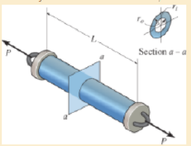
The pipe with two rigid caps attached to its ends is subjected to an axial force P. If the pipe is made from a material having a modulus of elasticity E and Poisson’s ratio v, determine the change in volume of the material.
Expert Solution & Answer
Want to see the full answer?
Check out a sample textbook solution
Students have asked these similar questions
Qf, Qa,Qm, Qcon,Qfg, Qbd, Qref,Qloss ( meaning, formula, percentage, and importance of higher value na qf, qa etc)
The beam is supported by a fixed support at point C and a roller at point A. It also has an internal hinge at point B. The beam supports a point load at point D, a moment at point A and a distributed load on segment BC.
a. calculate the support reactions at points A and C
b. calculate the internal resultant loadings (N, V, M) at points E and F, which lies in the middle between points A and D
P = 4 kip
Ma = 5 kip-ft
w1 = 3 kip/ft and w2 = 4 kip/ft
a = 3 ft
From the image of the pyramid, I want to find what s1 hat, s2 hat, and s3 hat are. I think s3 hat is just equal to e3 hat right? What about the others?
Chapter 3 Solutions
Mechanics of Materials (10th Edition)
Ch. 3.4 - Define a homogeneous material.Ch. 3.4 - Indicate the points on the stress-strain diagram...Ch. 3.4 - Define the modulus of elasticity E.Ch. 3.4 - At room temperature, mild steel is a ductile...Ch. 3.4 - Engineering stress and strain are calculated using...Ch. 3.4 - As the temperature increases the modulus of...Ch. 3.4 - A 100-mm-long rod has a diameter of 15 mm. If an...Ch. 3.4 - A bar has a length of 8 in. and cross-sectional...Ch. 3.4 - A 10-mm-diameter rod has a modulus of elasticity...Ch. 3.4 - The material for the 50-mm-long specimen has the...
Ch. 3.4 - The material for the 50-mm-long specimen has the...Ch. 3.4 - If the elongation of wire BC is 0.2 mm after the...Ch. 3.4 - A tension test was performed on a steel specimen...Ch. 3.4 - Data taken from a stress-strain test for a ceramic...Ch. 3.4 - Data taken from a stress-strain test for a ceramic...Ch. 3.4 - The stress-strain diagram for a steel alloy having...Ch. 3.4 - The stress-strain diagram for a steel alloy having...Ch. 3.4 - The stress-strain diagram for a steel alloy having...Ch. 3.4 - The rigid beam is supported by a pin at C and an...Ch. 3.4 - The rigid beam is supported by a pin at C and an...Ch. 3.4 - Acetal plastic has a stress-strain diagram as...Ch. 3.4 - The stress-strain diagram for an aluminum alloy...Ch. 3.4 - The stress-strain diagram for an aluminum alloy...Ch. 3.4 - The stress-strain diagram for an aluminum alloy...Ch. 3.4 - A bar having a length of 5 in. and cross-sectional...Ch. 3.4 - The rigid pipe is supported by a pin at A and an...Ch. 3.4 - The rigid pipe is supported by a pin at A and an...Ch. 3.4 - Direct tension indicators are sometimes used...Ch. 3.4 - The rigid beam is supported by a pin at C and an...Ch. 3.4 - The rigid beam is supported by a pin at C and an...Ch. 3.4 - The stress-strain diagram for a bone is shown, and...Ch. 3.4 - The stress-strain diagram for a bone is shown and...Ch. 3.4 - The two bars are made of a material that has the...Ch. 3.4 - The two bars are made of a material that has the...Ch. 3.4 - The pole is supported by a pin at C and an A-36...Ch. 3.4 - The bar DA is rigid and is originally held in the...Ch. 3.7 - A 100-mm-long rod has a diameter of 15 mm. If an...Ch. 3.7 - A solid circular rod that is 600 mm long and 20 mm...Ch. 3.7 - A 20-mm-wide block is firmly bonded to rigid...Ch. 3.7 - A 20-mm-wide block is bonded to rigid plates at...Ch. 3.7 - The acrylic plastic rod is 200 mm long and 15 mm...Ch. 3.7 - The plug has a diameter of 30 mm and fits within a...Ch. 3.7 - The elastic portion of the stress-strain diagram...Ch. 3.7 - The elastic portion of the stress-strain diagram...Ch. 3.7 - The brake pads for a bicycle tire are made of...Ch. 3.7 - The lap joint is connected together using a 1.25...Ch. 3.7 - The lap joint is connected together using a 1.25...Ch. 3.7 - The rubber block is subjected to an elongation of...Ch. 3.7 - The shear stress-strain diagram for an alloy is...Ch. 3.7 - A shear spring is made from two blocks of rubber,...Ch. 3 - The elastic portion of the tension stress-strain...Ch. 3 - The elastic portion of the tension stress-strain...Ch. 3 - The rigid beam rests in the horizontal position on...Ch. 3 - The wires each have a diameter of 12 in., length...Ch. 3 - The wires each have a diameter of 12 in., length...Ch. 3 - diameter steel bolts. If the clamping force in...Ch. 3 - The stress-strain diagram for polyethylene, which...Ch. 3 - The pipe with two rigid caps attached to its ends...Ch. 3 - The 8-mm-diameter bolt is made of an aluminum...Ch. 3 - An acetal polymer block is fixed to the rigid...
Knowledge Booster


Learn more about
Need a deep-dive on the concept behind this application? Look no further. Learn more about this topic, mechanical-engineering and related others by exploring similar questions and additional content below.Similar questions
- Question 1. A tube rotates in the horizontal ry plane with a constant angular velocity w about the z-axis. A particle of mass m is released from a radial distance R when the tube is in the position shown. This problem is based on problem 3.2 in the text. R m 2R Figure 1 x a) Draw a free body diagram of the particle if the tube is frictionless. b) Draw a free body diagram of the particle if the coefficient of friction between the sides of the tube and the particle is = k = p. c) For the case where the tube is frictionless, what is the radial speed at which the particle leaves the tube? d) For the case where there is friction, derive a differential equation that would allow you to solve for the radius of the particle as a function of time. I'm only looking for the differential equation. DO NOT solve it. 1 e) If there is no friction, what is the angle of the tube when the particle exits? • Hint: You may need to solve a differential equation for the last part. The "potentially useful…arrow_forwardQuestion 2. A smooth uniform sphere of mass m and radius r is squeezed between two massless levers, each of length 1, which are inclined at an angle with the vertical. A mechanism at pivot point O ensures that the angles & remain the same at all times so that the sphere moves straight upward. This problem is based on Problem 3-1 in the text. P P r Figure 2 a) Draw appropriate freebody diagrams of the system assuming that there is no friction. b) Draw appropriate freebody diagrams of the system assuming that there is a coefficient of friction between the sphere and the right lever of μ. c) If a force P is applied between the ends of the levers (shown in the diagram), and there is no friction, what is the acceleration of the sphere when = 30°arrow_forwardIf you had a matrix A = [1 2 3; 4 5 6; 7 8 9] and a matrix B = [1 2 3], how would you cross multiply them i.e. what is the cross product of AxB. what would be the cross product of a dyadic with a vector?arrow_forward
- Problem 3: The inertia matrix can be written in dyadic form which is particularly useful when inertia information is required in various vector bases. On the next page is a right rectangular pyramid of total mass m. Note the location of point Q. (a) Determine the inertia dyadic for the pyramid P, relative to point Q, i.e., 7%, for unit vectors ₁₁, 2, 3.arrow_forwardCan you solve for v? Also, what is A x uarrow_forwardThe external loads on the element shown below at the free end are F = 1.75 kN, P = 9.0 kN, and T = 72 Nm. The tube's outer diameter is 50 mm and the inner diameter is 45 mm. Given: A(the cross-sectional area) is 3.73 cm², Moment inertial I is 10.55 cm4, and J polar moment inertial is 21.1 cm4. Determine the following. (1) The critical element(s) of the bar. (2) Show the state of stress on a stress element for each critical element. -120 mm- Farrow_forward
- A crate weighs 530 lb and is hung by three ropes attached to a steel ring at A such that the top surface is parallel to the xy plane. Point A is located at a height of h = 42 in above the top of the crate directly over the geometric center of the top surface. Use the dimensions given in the table below to determine the tension in each of the three ropes. 2013 Michael Swanbom ↑ Z C BY NC SA b x B у D Values for dimensions on the figure are given in the following table. Note the figure may not be to scale. Variable Value a 30 in b 43 in с 4.5 in The tension in rope AB is lb The tension in rope AC is lb The tension in rope AD is lbarrow_forwardThe airplane weighs 144100 lbs and flies at constant speed and trajectory given by 0 on the figure. The plane experiences a drag force of 73620 lbs. a.) If = 11.3°, determine the thrust and lift forces required to maintain this speed and trajectory. b.) Next consider the case where is unknown, but it is known that the lift force is equal to 7.8 times the quantity (Fthrust Fdrag). Compute the resulting trajectory angle - and the lift force in this case. Use the same values for the weight and drag forces as you used for part a. Уллу Fdrag 10. Ө Fthrust cc 10 2013 Michael Swanbom BY NC SA Flift Fweight The lift force acts in the y' direction. The weight acts in the negative y direction. The thrust and drag forces act in the positive and negative x' directions respectively. Part (a) The thrust force is equal to lbs. The lift force is equal to Part (b) The trajectory angle is equal to deg. The lift force is equal to lbs. lbs.arrow_forwardThe hoist consists of a single rope and an arrangement of frictionless pulleys as shown. If the angle 0 = 59°, determine the force that must be applied to the rope, Frope, to lift a load of 4.4 kN. The three-pulley and hook assembly at the center of the system has a mass of 22.5 kg with a center of mass that lies on the line of action of the force applied to the hook. e ΘΕ B CC 10 BY NC SA 2013 Michael Swanbom Fhook Note the figure may not be to scale. Frope = KN HO Fropearrow_forward
arrow_back_ios
SEE MORE QUESTIONS
arrow_forward_ios
Recommended textbooks for you
 Elements Of ElectromagneticsMechanical EngineeringISBN:9780190698614Author:Sadiku, Matthew N. O.Publisher:Oxford University Press
 Mechanics of Materials (10th Edition)Mechanical EngineeringISBN:9780134319650Author:Russell C. HibbelerPublisher:PEARSON
 Thermodynamics: An Engineering ApproachMechanical EngineeringISBN:9781259822674Author:Yunus A. Cengel Dr., Michael A. BolesPublisher:McGraw-Hill Education
 Control Systems EngineeringMechanical EngineeringISBN:9781118170519Author:Norman S. NisePublisher:WILEY
 Mechanics of Materials (MindTap Course List)Mechanical EngineeringISBN:9781337093347Author:Barry J. Goodno, James M. GerePublisher:Cengage Learning
 Engineering Mechanics: StaticsMechanical EngineeringISBN:9781118807330Author:James L. Meriam, L. G. Kraige, J. N. BoltonPublisher:WILEY
Elements Of Electromagnetics
Mechanical Engineering
ISBN:9780190698614
Author:Sadiku, Matthew N. O.
Publisher:Oxford University Press
Mechanics of Materials (10th Edition)
Mechanical Engineering
ISBN:9780134319650
Author:Russell C. Hibbeler
Publisher:PEARSON
Thermodynamics: An Engineering Approach
Mechanical Engineering
ISBN:9781259822674
Author:Yunus A. Cengel Dr., Michael A. Boles
Publisher:McGraw-Hill Education
Control Systems Engineering
Mechanical Engineering
ISBN:9781118170519
Author:Norman S. Nise
Publisher:WILEY
Mechanics of Materials (MindTap Course List)
Mechanical Engineering
ISBN:9781337093347
Author:Barry J. Goodno, James M. Gere
Publisher:Cengage Learning
Engineering Mechanics: Statics
Mechanical Engineering
ISBN:9781118807330
Author:James L. Meriam, L. G. Kraige, J. N. Bolton
Publisher:WILEY
EVERYTHING on Axial Loading Normal Stress in 10 MINUTES - Mechanics of Materials; Author: Less Boring Lectures;https://www.youtube.com/watch?v=jQ-fNqZWrNg;License: Standard YouTube License, CC-BY