
Mechanics of Materials (10th Edition)
10th Edition
ISBN: 9780134319650
Author: Russell C. Hibbeler
Publisher: PEARSON
expand_more
expand_more
format_list_bulleted
Concept explainers
Videos
Textbook Question
Chapter 3.4, Problem 3.2P
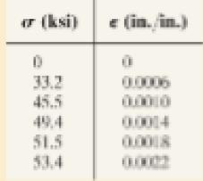
Data taken from a stress-strain test for a ceramic are given in the table. The curve is linear between the origin and the first point. Plot the diagram, and determine the modulus of elasticity and the modulus of resilience.
Expert Solution & Answer

Trending nowThis is a popular solution!

Students have asked these similar questions
reading is 0.4 mas SHOWN.
Assume h₁ = 0.4 m, h₂ = 0.5 m.
(a) Do you know the specific weight of mercury?
(b) Do you know the specific weight of gasoline?
(c) Do you know the specific weight of oil?
(a) YHg
=
133,000
(b) Ygas
= 6867
(c) Yoil =
8829
eTextbook and Media
Part 2
N/m³
N/m³
N/m³
A+
Gasoline
t
+B
Oil
-Mercury
Attempts: unlimited
Did you calculate the pressure difference between two locations using the correct specific weight?
Did you assume that the pressures in fluid are the same in a horizontal plane even though they are in different tubes?
Are the calculated pressures in a column of fluid always higher at lower elevations?
Did you account for the fact that the two horizontal tubes of the U-tube are above the ground?
Concepts: The pressure in a fluid is a function of the specific weight of the fluid and the height relative to a reference.
Pressure is constant in a horizontal plane of a continuous mass of fluid.
(a) What is the initial pressure difference? (PA-PB)
(b) What is…
Find the solution of the following Differential Equations
1)
"-4y+3y=0
3) "+16y=0
2) y"-16y=0
4) y"-y-6y=0
5) y"+2y=0
7) y"+y=0, (#0)
9) y"-y=0, y(0) = 6, y'(0) = -4
11) y"-4y+3y=0, y(0)=-1,
13)
y'(0) = -5
"+2y+2y=0
15) y"-9y=0
17) y"-4y=0
6) y"-2y+2y=0
8)
"+4y+5y=0
10) y"-9y=0, y(0) = 2, y'(0) = 0
12) y"-3y+2y= 0, y(0)=-1,
y'(0) = 0
14) 4y+4y+y=0
16) "+6y+12y=0
18) 4y+4y+17y=0
Access Pearson
Mastering Engineering
Back to my courses
Course Home
Course Home
Scores
Chapter 3 Solutions
Mechanics of Materials (10th Edition)
Ch. 3.4 - Define a homogeneous material.Ch. 3.4 - Indicate the points on the stress-strain diagram...Ch. 3.4 - Define the modulus of elasticity E.Ch. 3.4 - At room temperature, mild steel is a ductile...Ch. 3.4 - Engineering stress and strain are calculated using...Ch. 3.4 - As the temperature increases the modulus of...Ch. 3.4 - A 100-mm-long rod has a diameter of 15 mm. If an...Ch. 3.4 - A bar has a length of 8 in. and cross-sectional...Ch. 3.4 - A 10-mm-diameter rod has a modulus of elasticity...Ch. 3.4 - The material for the 50-mm-long specimen has the...
Ch. 3.4 - The material for the 50-mm-long specimen has the...Ch. 3.4 - If the elongation of wire BC is 0.2 mm after the...Ch. 3.4 - A tension test was performed on a steel specimen...Ch. 3.4 - Data taken from a stress-strain test for a ceramic...Ch. 3.4 - Data taken from a stress-strain test for a ceramic...Ch. 3.4 - The stress-strain diagram for a steel alloy having...Ch. 3.4 - The stress-strain diagram for a steel alloy having...Ch. 3.4 - The stress-strain diagram for a steel alloy having...Ch. 3.4 - The rigid beam is supported by a pin at C and an...Ch. 3.4 - The rigid beam is supported by a pin at C and an...Ch. 3.4 - Acetal plastic has a stress-strain diagram as...Ch. 3.4 - The stress-strain diagram for an aluminum alloy...Ch. 3.4 - The stress-strain diagram for an aluminum alloy...Ch. 3.4 - The stress-strain diagram for an aluminum alloy...Ch. 3.4 - A bar having a length of 5 in. and cross-sectional...Ch. 3.4 - The rigid pipe is supported by a pin at A and an...Ch. 3.4 - The rigid pipe is supported by a pin at A and an...Ch. 3.4 - Direct tension indicators are sometimes used...Ch. 3.4 - The rigid beam is supported by a pin at C and an...Ch. 3.4 - The rigid beam is supported by a pin at C and an...Ch. 3.4 - The stress-strain diagram for a bone is shown, and...Ch. 3.4 - The stress-strain diagram for a bone is shown and...Ch. 3.4 - The two bars are made of a material that has the...Ch. 3.4 - The two bars are made of a material that has the...Ch. 3.4 - The pole is supported by a pin at C and an A-36...Ch. 3.4 - The bar DA is rigid and is originally held in the...Ch. 3.7 - A 100-mm-long rod has a diameter of 15 mm. If an...Ch. 3.7 - A solid circular rod that is 600 mm long and 20 mm...Ch. 3.7 - A 20-mm-wide block is firmly bonded to rigid...Ch. 3.7 - A 20-mm-wide block is bonded to rigid plates at...Ch. 3.7 - The acrylic plastic rod is 200 mm long and 15 mm...Ch. 3.7 - The plug has a diameter of 30 mm and fits within a...Ch. 3.7 - The elastic portion of the stress-strain diagram...Ch. 3.7 - The elastic portion of the stress-strain diagram...Ch. 3.7 - The brake pads for a bicycle tire are made of...Ch. 3.7 - The lap joint is connected together using a 1.25...Ch. 3.7 - The lap joint is connected together using a 1.25...Ch. 3.7 - The rubber block is subjected to an elongation of...Ch. 3.7 - The shear stress-strain diagram for an alloy is...Ch. 3.7 - A shear spring is made from two blocks of rubber,...Ch. 3 - The elastic portion of the tension stress-strain...Ch. 3 - The elastic portion of the tension stress-strain...Ch. 3 - The rigid beam rests in the horizontal position on...Ch. 3 - The wires each have a diameter of 12 in., length...Ch. 3 - The wires each have a diameter of 12 in., length...Ch. 3 - diameter steel bolts. If the clamping force in...Ch. 3 - The stress-strain diagram for polyethylene, which...Ch. 3 - The pipe with two rigid caps attached to its ends...Ch. 3 - The 8-mm-diameter bolt is made of an aluminum...Ch. 3 - An acetal polymer block is fixed to the rigid...
Knowledge Booster


Learn more about
Need a deep-dive on the concept behind this application? Look no further. Learn more about this topic, mechanical-engineering and related others by exploring similar questions and additional content below.Similar questions
- Access Pearson Mastering Engineering Back to my courses Course Home Course Home Scores Review Next >arrow_forwardAccess Pearson Course Home Scoresarrow_forwardAccess Pearson Mastering Engineering Back to my courses Course Home Course Home Scoresarrow_forwardCan you answer this question?arrow_forwardA gear has a gear wheel with 16 teeth. The gear should be dimensioned for the highest and lowest gear ratio. Looking for output power, torque, speed?nin= 2000 rpmmin = 30Nmn=0,9a max= 450 mmModule 4Gear limitsz1 z213 13-1614 14-2615 15-4516 16-10117 17-131418 18-…..I have calculate but I can’t get the right answers…..√16 =459x60/56x57=1.1 lowest59x60/13x13=20,94 highestnut=2000/1.1= 1818rpmnut=2000/20.94=95.5 rpmMut=1.1x30=33 NmMut=20.94x30=628,2 Nm(Right answer)LowestZ=13, M=24,4Nm, n=2462 rpmHighestZ=92, M=172,5Nm, n=347,8 rpmP=5655W on botharrow_forwardPlease see attached pic.arrow_forwardarrow_back_iosSEE MORE QUESTIONSarrow_forward_ios
Recommended textbooks for you
 Elements Of ElectromagneticsMechanical EngineeringISBN:9780190698614Author:Sadiku, Matthew N. O.Publisher:Oxford University Press
 Mechanics of Materials (10th Edition)Mechanical EngineeringISBN:9780134319650Author:Russell C. HibbelerPublisher:PEARSON
 Thermodynamics: An Engineering ApproachMechanical EngineeringISBN:9781259822674Author:Yunus A. Cengel Dr., Michael A. BolesPublisher:McGraw-Hill Education
 Control Systems EngineeringMechanical EngineeringISBN:9781118170519Author:Norman S. NisePublisher:WILEY
 Mechanics of Materials (MindTap Course List)Mechanical EngineeringISBN:9781337093347Author:Barry J. Goodno, James M. GerePublisher:Cengage Learning
 Engineering Mechanics: StaticsMechanical EngineeringISBN:9781118807330Author:James L. Meriam, L. G. Kraige, J. N. BoltonPublisher:WILEY
Elements Of Electromagnetics
Mechanical Engineering
ISBN:9780190698614
Author:Sadiku, Matthew N. O.
Publisher:Oxford University Press
Mechanics of Materials (10th Edition)
Mechanical Engineering
ISBN:9780134319650
Author:Russell C. Hibbeler
Publisher:PEARSON
Thermodynamics: An Engineering Approach
Mechanical Engineering
ISBN:9781259822674
Author:Yunus A. Cengel Dr., Michael A. Boles
Publisher:McGraw-Hill Education
Control Systems Engineering
Mechanical Engineering
ISBN:9781118170519
Author:Norman S. Nise
Publisher:WILEY
Mechanics of Materials (MindTap Course List)
Mechanical Engineering
ISBN:9781337093347
Author:Barry J. Goodno, James M. Gere
Publisher:Cengage Learning
Engineering Mechanics: Statics
Mechanical Engineering
ISBN:9781118807330
Author:James L. Meriam, L. G. Kraige, J. N. Bolton
Publisher:WILEY
Material Properties 101; Author: Real Engineering;https://www.youtube.com/watch?v=BHZALtqAjeM;License: Standard YouTube License, CC-BY