
Videos
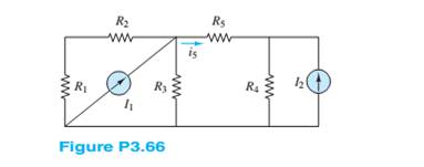
Find the Norton equivalent of the network seen by
Want to see the full answer?
Check out a sample textbook solution
Chapter 3 Solutions
Principles and Applications of Electrical Engineering


- Draw the complete circular stator winding for a three phase delta connected AC generator consisting of 4 poles and 24 slots using a parallel connection. Your submission must consist of two drawings as follows: One drawing must show the winding arrangement of the phasegroups in the slots of the stator highlighting the start and finish of each phasegroup The other drawing must show only the end connections of each phase group for a parallel connection of the phasegroups and a delta connection of the phases The use of AutoCad or any other software is encouraged.arrow_forward1. For v(t)=2Σn-[8(t-n) + 28(t-n-0.4)], determine (a) (10%) a figure of v(t); (b) (5%) period To; (c) (10%) Fourier series in Form III; (d) (5%) Fourier transform; (e) (5%) total power.arrow_forward5. In the figure, v(t) = m(t)ej2nfct where the message signal is m(t): = Acos (2πfmt) and the carrier signal is vc(t) = 2e−j(2nfct+0) where 0 is constant and 0 < fmarrow_forward= cos (2π x 10t+ 0) where 0 is random with a probability density E [0, 2π), and f(0) = 0 otherwise. v,(t) passes through a linear filter below. 2. Consider a random process v(t) function f(0) = 1/(2) for vi(t)- H(f) vo(t) Determine (a) (5%) vo(t); (b) (10%) autocorrelation function of v(t); (c) (8%) power spectral density function of vo(t); (d) (7%) power of vo(t). 1 = H(f) 2πf2+1arrow_forward4. Consider v(t) = 2 cos(t) + 5 sin(2t) passes through a linear system with frequence response H(f). 3 vi(t) Determine (a) (10%) vo(t); (b) (5%) power of vo(t). H(f) → vo(t) H(f)= 3, Ifls- 4π (0, otherwise.arrow_forward3. For the AM demodulator in figure, v(t) = m(t)cos (2πfet + 4) with a constant where the message signal is m(t) v(t)- =Acos (2πfmt) and carrier signal is v(t) = cos (2πfet) with fmarrow_forwardNot use ai pleasearrow_forward14arrow_forward5. In the figure, v(t) = m(t)ej2nfct where the message signal is m(t): = Acos (2πfmt) and the carrier signal is vc(t) = 2e−j(2nfct+0) where 0 is constant and 0 < fmarrow_forwardFor the following parallel resonant bandpass filter, find the exact center frequency of the pass band and the bandwidth. Given: • Vin = 20 V • L = 7.5 μH C = 270 pF - Rw = 5.1 Q R₁ = 750 0 Center Frequency: f= kHz Bandwidth: BW= kHz Maximum Output Voltage: Vout(max)= V Minimum Output Voltage: Vout(min) = V 270 pF HH C ww L Rw 5.1Q 7.5 HH Vin 20 V RLoad 750 Ω Voutarrow_forward3. For v(t) = 4Σn=-8(t-n- 0.5), (a) (10%) draw a figure of v(t); (b) (5%) determine period To; (c) (10%) determine Fourier transform form III; (d) (5%) determine power spectral density.arrow_forward1. For v(t) = 2 cos(2π x 20t) + 3 sin (2π x 10t), determine (a) (5%) period To; →→T= (b) (8%) Fourier transform form II; (c) (5%) power of the fundamental frequency component; (d) (2%) total power. s [ue] dtarrow_forwardarrow_back_iosSEE MORE QUESTIONSarrow_forward_iosRecommended textbooks for you
 Introductory Circuit Analysis (13th Edition)Electrical EngineeringISBN:9780133923605Author:Robert L. BoylestadPublisher:PEARSON
 Delmar's Standard Textbook Of ElectricityElectrical EngineeringISBN:9781337900348Author:Stephen L. HermanPublisher:Cengage Learning
 Programmable Logic ControllersElectrical EngineeringISBN:9780073373843Author:Frank D. PetruzellaPublisher:McGraw-Hill Education
 Fundamentals of Electric CircuitsElectrical EngineeringISBN:9780078028229Author:Charles K Alexander, Matthew SadikuPublisher:McGraw-Hill Education
 Electric Circuits. (11th Edition)Electrical EngineeringISBN:9780134746968Author:James W. Nilsson, Susan RiedelPublisher:PEARSON
 Engineering ElectromagneticsElectrical EngineeringISBN:9780078028151Author:Hayt, William H. (william Hart), Jr, BUCK, John A.Publisher:Mcgraw-hill Education,
Introductory Circuit Analysis (13th Edition)Electrical EngineeringISBN:9780133923605Author:Robert L. BoylestadPublisher:PEARSONDelmar's Standard Textbook Of ElectricityElectrical EngineeringISBN:9781337900348Author:Stephen L. HermanPublisher:Cengage LearningProgrammable Logic ControllersElectrical EngineeringISBN:9780073373843Author:Frank D. PetruzellaPublisher:McGraw-Hill EducationFundamentals of Electric CircuitsElectrical EngineeringISBN:9780078028229Author:Charles K Alexander, Matthew SadikuPublisher:McGraw-Hill EducationElectric Circuits. (11th Edition)Electrical EngineeringISBN:9780134746968Author:James W. Nilsson, Susan RiedelPublisher:PEARSONEngineering ElectromagneticsElectrical EngineeringISBN:9780078028151Author:Hayt, William H. (william Hart), Jr, BUCK, John A.Publisher:Mcgraw-hill Education,Mesh Current Problems in Circuit Analysis - Electrical Circuits Crash Course - Beginners Electronics; Author: Math and Science;https://www.youtube.com/watch?v=DYg8B-ElK0s;License: Standard Youtube License