
Concept explainers
Videos
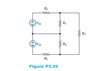
For the circuit of Figure P3.22 determine:
a. The most efficient way to solve for the voltage a cross
b. The voltage across
Want to see the full answer?
Check out a sample textbook solution
Chapter 3 Solutions
Principles and Applications of Electrical Engineering


- 7.2 At t = 0, the switch in the circuit shown moves instantaneously from position a to position b. a) Calculate v, for t≥ 0. b) What percentage of the initial energy stored in the inductor is eventually dissipated in the 4 resistor? 6Ω a w + 10 0.32 H3 403 6.4 A =0 b Answer: (a) -8e-10 V, t = 0; (b) 80%.arrow_forwardAt t = 0, the switch closes. Find the IL(t) and VL(t) for t≥ 0 in t and s domain. Can you help me? 1) (+. 24V ง Anahtar t=0 anında kapatılıyor. to icin TL(t) ve bulunuz. J 3√√√2 ww مفروم + t=0 $6.5 5H VLCH) 2.2 Vilt)arrow_forward"For the network in the figure, determine RE and RB if A₁ Zb = BRE." = -10 and re = 3.8. Assume thatarrow_forward
- 2.a. Simplify and determine Zk+ for: 2.x. 60 [Hz] ⚫ 2.y. 180 [Hz] a.x. 60[Hz] a.y. 180 [Hz] Joo (127 2[H] w 240 [√]arrow_forwardP3. Given the following network, determine: ⚫ 3.a. Equivalent Y ⚫ 3.b. Equivalent A 2 R[2] 10 8 b 20 30 5arrow_forward[Electrical Circuits] P1. Using the mesh current method, calculate the magnitude and direction of: 1.a. I and I (mesh currents) 1.b. I10 (test current in R10 = 1082) 1.c. (Calculate the magnitude and signs of V10) 6[A] 12 [√] بي 10 38 20 4A] Iw -800arrow_forward
- Need handwritten solution do not use chatgptarrow_forward[07/01, 16:59] C P: Question: Calculate the following for 100Hz and 500Hz (express all answers in phasor form). Show all work. A) Xc and ZTB) VR1 and VC1 C) IT Handwritten Solution Pleasearrow_forward1. Sketch the root loci of a system with the following characteristic equation: s²+2s+2+K(s+2)=0 2. Sketch the root loci for the following loop transfer function: KG(s)H(s)=- K(s+1) s(s+2)(s²+2s+4)arrow_forward
- 3. For the unity feedback system with forward path transfer function, G(s), below: G(s)= K(s² +8) (s+4)(s+5) Sketch the root locus and show the breakaway/break-in point(s) and jo-axis crossing. Determine the angle of arrival and K value at the breakaway/break- in point(s). Give your comment the system is stable or unstable.arrow_forwardFind the step response of each of the transfer functions shown in Eqs. (4.62) through (4.64) and compare them. [Shown in the image]Book: Norman S. Nise - Control Systems Engineering, 6th EditionTopic: Chapter-4: Time Response, Example 4.8Solve the math with proper explanation. Please don't give AI response. Asking for a expert verified answer.arrow_forward2. With respect to the circuit shown in Figure 2 below V2 -R1 R2 R4 w R3 R5 Figure 2: DC Circuit 2 a. Using Ohm's and Kirchhoff's laws calculate the current flowing through R3 and so determine wattage rating of R3. b. Verify your results with simulations. Note: you must use the values for the components in Table 2. Table 2 V2 (Volts) R1 (KQ) R2 (KQ) R3 (KQ) R4 (KQ) R5 (KQ) 9 3.3 5 10 6 1 3.3arrow_forward
 Introductory Circuit Analysis (13th Edition)Electrical EngineeringISBN:9780133923605Author:Robert L. BoylestadPublisher:PEARSON
 Delmar's Standard Textbook Of ElectricityElectrical EngineeringISBN:9781337900348Author:Stephen L. HermanPublisher:Cengage Learning
 Programmable Logic ControllersElectrical EngineeringISBN:9780073373843Author:Frank D. PetruzellaPublisher:McGraw-Hill Education
 Fundamentals of Electric CircuitsElectrical EngineeringISBN:9780078028229Author:Charles K Alexander, Matthew SadikuPublisher:McGraw-Hill Education
 Electric Circuits. (11th Edition)Electrical EngineeringISBN:9780134746968Author:James W. Nilsson, Susan RiedelPublisher:PEARSON
 Engineering ElectromagneticsElectrical EngineeringISBN:9780078028151Author:Hayt, William H. (william Hart), Jr, BUCK, John A.Publisher:Mcgraw-hill Education,