
Concept explainers
Find the Thé’cnin equivalent resistance seen by
The Thevenin equivalent resistance seen by
Answer to Problem 3.65HP
The Thevenin equivalent resistance seen by the resistance
Explanation of Solution
Calculation:
The given diagram is shown in Figure 1
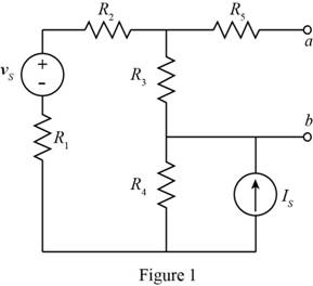
To calculate the Thevenin resistance, open circuit current source and short circuit the voltage source, the redraw the circuit.
The required diagram is shown in Figure 2
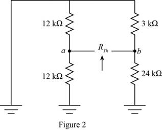
From above the equivalent resistance of the circuit is evaluated as,
Mark the values and redraw the given circuit.
The required diagram is shown in Figure 3
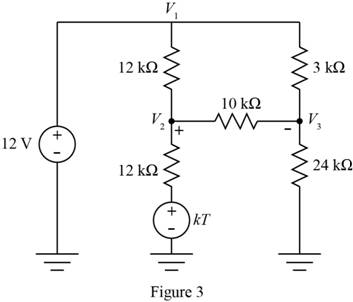
From the above figure the node voltage
The expression for the voltage
Apply KVL at node
Subsitue
Substitute
Substitute
Apply KVL to the node
Substitute
To obtain the equivalent Thevenin resistance of the circuit open circuit the load terminals, short circuit the voltage source and redraw the circuit.
The required diagram is shown in Figure 4
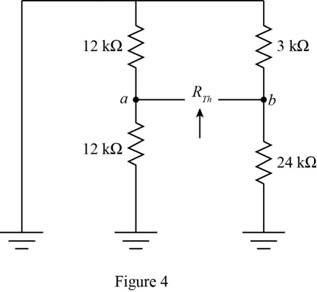
From the above circuit, the equivalent resistance is calculated as,
To obtain the Thevenin equivalent voltage between the terminals, open circuit the load terminals and redraw the circuit.
The required diagram is shown in Figure 5
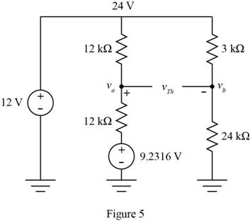
From the above circuit, the node voltage
The current through the resistance of
From above circuit, the node voltage
Substitute
The expression to calculate the Thevenin equivalent voltage is given by,
Substitute
The expression to calculate the Norton equivalent current is given by,
Substitute
Conclusion:
Therefore, the Thevenin equivalent resistance seen by the resistance
Want to see more full solutions like this?
Chapter 3 Solutions
Principles and Applications of Electrical Engineering
- I need help with this problem and an explanation of the solution for the image described below. (Introduction to Signals and Systems)arrow_forwardDetermine the eigenvalues and eigenvectors of using Gauss elimination -3 1 -3 A = = 20 3 10 2 -2 4arrow_forward[3 1 41 find Eigen values and Eigen Vector for A=0 26 LO 0 5arrow_forward
 Introductory Circuit Analysis (13th Edition)Electrical EngineeringISBN:9780133923605Author:Robert L. BoylestadPublisher:PEARSON
 Delmar's Standard Textbook Of ElectricityElectrical EngineeringISBN:9781337900348Author:Stephen L. HermanPublisher:Cengage Learning
 Programmable Logic ControllersElectrical EngineeringISBN:9780073373843Author:Frank D. PetruzellaPublisher:McGraw-Hill Education
 Fundamentals of Electric CircuitsElectrical EngineeringISBN:9780078028229Author:Charles K Alexander, Matthew SadikuPublisher:McGraw-Hill Education
 Electric Circuits. (11th Edition)Electrical EngineeringISBN:9780134746968Author:James W. Nilsson, Susan RiedelPublisher:PEARSON
 Engineering ElectromagneticsElectrical EngineeringISBN:9780078028151Author:Hayt, William H. (william Hart), Jr, BUCK, John A.Publisher:Mcgraw-hill Education,


