
Concept explainers
Videos
The Norton and Thevenin equivalent networks from node
Answer to Problem 3.71HP
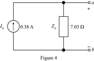
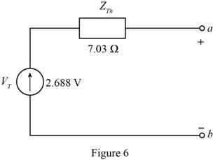
The Thevenin equivalent Network is shown in Figure 6 and the Norton equivalent network is shown in Figure 4
Explanation of Solution
Calculation:
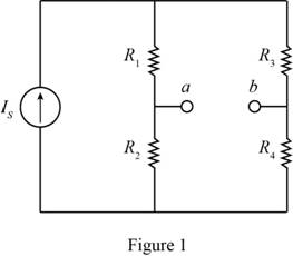
The given diagram is shown in Figure 1
To determine the Norton equivalent, short circuit the output terminals, Mark the values, current direction, and redraw the circuit.
The required diagram is shown in Figure 2
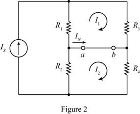
Apply KVL to the first loop.
Apply KVL to the second loop.
The equation for the Norton current is given by,
Substitute
To obtain the Norton resistance of the circuit, short circuit the voltage source, open circuit the current source and redraw the circuit.
The required diagram is shown in Figure 3
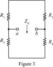
Form the above circuit the Norton impedance of the circuit is calculated as,
Substitute
Mark the values and draw the Norton equivalent circuit.
The required diagram is shown in Figure 4
To calculate the Thevenin voltage, remove the load resistance and redraw the circuit.
The required diagram is shown in Figure 5
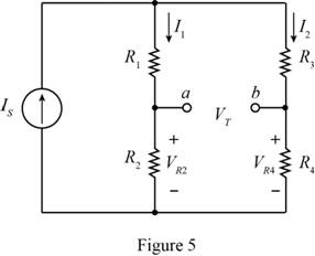
From the above circuit the value of the current
Substitute
The expression for the value of the current
Substitute
The expression for the voltage across the resistor
Substitute
The expression for the voltage across the resistor
Substitute
From Figure (5), the expression for the Thevenin voltage is given by,
Substitute
The Thevenin and the Norton resistance of the circuit are equal, thus the expression for the Thevenin resistance is given by,
Substitute
Mark the values and draw the Thevenin equivalent of the circuit.
The required diagram is shown in Figure 6
Conclusion:
Therefore, the Thevenin equivalent Network is shown in Figure 6 and the Norton equivalent network is shown in Figure 4
Want to see more full solutions like this?
Chapter 3 Solutions
Principles and Applications of Electrical Engineering


- Many machines, such as lathes, milling machines, and grinders, are equipped with tracers to reproduce the contours of templates. The figure is a schematic diagram of a hydraulic tracer in which the tool duplicates the shape of the template on the workpiece. a) Explain how the system works. b) Draw a block diagram and identify the system's elements. c) Classify the control system. Oil under pressure Template Style Tool Piece of workarrow_forward2. Refrigerators to maintain the product at a given temperature have a control system. a) Explain how the control system is or how you think it should be (Make a diagram). b) Make the typical block diagram of a control system and identify the components in the refrigerator system. c) Classify the control system.arrow_forward3. Internal combustion engines require a cooling system to function properly, which maintains the engine temperature at an appropriate value. Neither too high nor too low. There are several systems to control this temperature, the two best known are: • The classic one that uses a thermostat that regulates the flow of coolant (water), and where the fan is mechanically coupled to the engine. • In more recent vehicles, in addition to the thermostat, a temperature controller is used that turns an electric fan on and off. Select one of the two systems mentioned above and: a) Explain how it works, using diagrams. b) Make the typical block diagram of a feedback control system, identifying the components of the system. c) Classify the control system.arrow_forward
- A 3-phase, star connected, 10 kVA, 380 V, salient pole alternator with direct and quadrature axis reactances of 15 and 8 0/ph respectively, delivers full-load current at 0.8 power factor lagging. Neglect the armature resistance. Determine the following: (a) The load angle, (b) The direct axis and quadrature axis components of armature current, (c) E.M.F induced voltage of the alternator, (d) The voltage regulation, and (e) The developed power by the alternator?arrow_forwardA 2000 kVA,Y- connected alternator gives an open circuit line voltage of 3.3 kV for a field current of 65 A. For same field current the short circuit current is being equal to full load current. Calculate the full load voltage regulation at both 0.8 lagging p.f. and unity p.f., neglect armature resistance?arrow_forwardDon't use ai to answer I will report you answerarrow_forward
 Introductory Circuit Analysis (13th Edition)Electrical EngineeringISBN:9780133923605Author:Robert L. BoylestadPublisher:PEARSON
 Delmar's Standard Textbook Of ElectricityElectrical EngineeringISBN:9781337900348Author:Stephen L. HermanPublisher:Cengage Learning
 Programmable Logic ControllersElectrical EngineeringISBN:9780073373843Author:Frank D. PetruzellaPublisher:McGraw-Hill Education
 Fundamentals of Electric CircuitsElectrical EngineeringISBN:9780078028229Author:Charles K Alexander, Matthew SadikuPublisher:McGraw-Hill Education
 Electric Circuits. (11th Edition)Electrical EngineeringISBN:9780134746968Author:James W. Nilsson, Susan RiedelPublisher:PEARSON
 Engineering ElectromagneticsElectrical EngineeringISBN:9780078028151Author:Hayt, William H. (william Hart), Jr, BUCK, John A.Publisher:Mcgraw-hill Education,