
Concept explainers
Videos
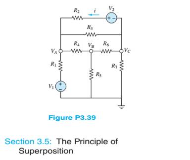
Use nodal analysis in the circuit of Figure P3.39 tofind the three indicated node voltages and the current i.Assume:
Want to see the full answer?
Check out a sample textbook solution
Chapter 3 Solutions
Principles and Applications of Electrical Engineering


- According to the circuit and parameters given in the figure, make your calculations and write the table. wmww w n ww bbn m w w w w Please fill in. www ww w +12V +12V M1 M2 2kN 10kN K ImA/V² 0.5mA/V² VTH 2V 1.5V 22kN M2 MODE 33k2 M1 Ip 1kN VGS Vps K1=lmA/V² Vth1=2V; M2: K2=0.5mA/V² VTH2=1.5Varrow_forwardRefer to the given circuit below. Using Superposition Theorem, determine the percent contribution of E₁ to the current through R3 (lbc)- R3E1 % contribution = x 100 R3E1+1R3E2+¹R31 R1 R2 R3 R4 E₁ E2 T 8 Ω 6Q 4Q 7 V 11 V 5 A R₂ C ΤΩ R₁ E₁ a b R3 RA E₂arrow_forward4- In the circuit in following figure, obtain y 1, v2, and v3. 15 V 25 V 10 V 20 Varrow_forward
- b) For the circuit shown in Figure Q3b: i) Define coupling coefficient. ii) Find the voltage, Vx. j3 2 + Vx -A j4 Q j2 Q 520° V j5 Q j7 Q j1 0 12 12 Q Figure Q3barrow_forward8-13 E (a) Formulate mesh-current equations for the cir- cuit in Figure P3-13. (b) Formulate node-voltage equations for the circuit in Figure P3-13. (c) Which set of equations would be easier to solve? Why? (d) Using MATLAB, find , and i, in terms of the mesh- current variables. SSarrow_forwardQ3: Suppose that the components of the circuit shown in figure below have the following values: RI= SkD, R2= 9kΩ, R3-10kΩ , R4-5kΩ, R5-10kΩ, R6-9k Ω. The voltage across AB is measured by a voltmeter whose internal resistance is 95k2. What is the measurement error caused by the resistance of the measuring instrument? R3 Rs RM Ri SMA Fo Em Ry Barrow_forward
- 3.40 Find Vi and V in the circuit shown in Figure P340. FIGURE P3.40 2 kn R2 V2 4 kn 2000 i 5 V 3 kn 2.5 k 45arrow_forwardConsider the series-parallel circuit shown in the figure below with various multimeters connected in the circuit. Assum that XMM1 has been configured in ammeter mode, and XMM2 has been configured in voltmeter mode. XMM1 R1 1kQ XMM2 R2 R3 V1 1kQ 1kQ 12V 3.1: Redraw the circuit replacing XMM1 and XMM2 by their equivalent circuit models 3.2: Assume that XMM2 was incorrectly configured in ammeter mode. Redraw the equivalent circuit from 3.1 and compute the current that would be measured by the ammeter in this scenario. Hil-arrow_forwardRefer to the given circuit below. Using Superposition Theorem, determine the percent contribution of I to the current through R3 (lbc). IR31 % contribution = x 100 1 +1 +1 R3E1 "R3E2 R3 R4 E1 E2 I 6Q 1Q 9 V 7V 3A a R31 R1 2Q R1 R2 1Q E₁ R2 C b R3 R4 E2arrow_forward
- R1 D1 D2 R2 V1 V3 R3 V2 Rj=120 Q, R2=10 Q and R3=200 2, Vi= 10V and V2=15V, Dị and D2 (forward voltage drop) VF=0.8V a) Using mesh analysis to analyze the given circuit, derive the voltage V3. b) What is the state operation of Di and D2?arrow_forwardLE424 QUESTION 3 a) Using resistor nearest preferred values (NPV), design a network as shown in Figure Q3a if Vcc = 25 V, Vc = 10 V, Ica = 3 mA and IcSATURATION) = 1.5lco. Determine the values of RB, Rc, and RE and state all assumptions made. Vcc lo Rc RB ovc Vo Co Vio B = 100 RE Zo Figure Q3aarrow_forwardFind the Thevenin equivalent circuit to the LHS of AB of the DC network in Figure Q2. From the resulting Thevenin equivalent circuit find the Norton equivalent circuit. RI 300 Ω E 20 V R2 900 £2 Figure Q2 ww R3 -400 £2 www R4 250 Ω B RLarrow_forward
 Introductory Circuit Analysis (13th Edition)Electrical EngineeringISBN:9780133923605Author:Robert L. BoylestadPublisher:PEARSON
 Delmar's Standard Textbook Of ElectricityElectrical EngineeringISBN:9781337900348Author:Stephen L. HermanPublisher:Cengage Learning
 Programmable Logic ControllersElectrical EngineeringISBN:9780073373843Author:Frank D. PetruzellaPublisher:McGraw-Hill Education
 Fundamentals of Electric CircuitsElectrical EngineeringISBN:9780078028229Author:Charles K Alexander, Matthew SadikuPublisher:McGraw-Hill Education
 Electric Circuits. (11th Edition)Electrical EngineeringISBN:9780134746968Author:James W. Nilsson, Susan RiedelPublisher:PEARSON
 Engineering ElectromagneticsElectrical EngineeringISBN:9780078028151Author:Hayt, William H. (william Hart), Jr, BUCK, John A.Publisher:Mcgraw-hill Education,