
Principles and Applications of Electrical Engineering
6th Edition
ISBN: 9780073529592
Author: Giorgio Rizzoni Professor of Mechanical Engineering, James A. Kearns Dr.
Publisher: McGraw-Hill Education
expand_more
expand_more
format_list_bulleted
Concept explainers
Videos
Textbook Question
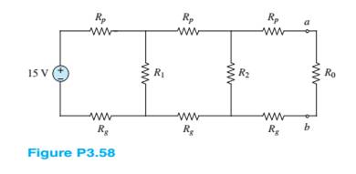
Chapter 3, Problem 3.58HP
Find the Thé venin equivalent network seen by theload
Expert Solution & Answer
Want to see the full answer?
Check out a sample textbook solution
Students have asked these similar questions
Find;-
magnitude of line voltages
Line currents
Verify that th eload is balanced, i.e In = 0
Don't use ai to answer I will report you answer
Don't use ai to answer I will report you answer
Chapter 3 Solutions
Principles and Applications of Electrical Engineering
Ch. 3 - Use node voltage analysis to find the voltages V1...Ch. 3 - Use node voltage analysis to find the voltages V1...Ch. 3 - Using node voltage analysis in the circuit of...Ch. 3 - Using node voltage analysis in the circuit of...Ch. 3 - In the circuit shown in Figure P3.5, the mesh...Ch. 3 - In the circuit shown in Figure P3.5, the source...Ch. 3 - Use nodal analysis in the circuit of Figure P3.7...Ch. 3 - Use mesh analysis in the circuit of Figure P3.7 to...Ch. 3 - Use nodal analysis in the circuit of Figure P3.9...Ch. 3 - Use nodal analysis in the circuit of Figure P3.10...
Ch. 3 - Use nodal analysis in the circuit of Figure P3.11...Ch. 3 - Find the power delivered to the load resistor R0...Ch. 3 - For the circuit of Figure P3.13, write the nodee...Ch. 3 - Using mesh analysis, find the currents i1 and i2...Ch. 3 - Using mesh analysis, find the currents i1 and i2...Ch. 3 - Using mesh analysis, find the voltage v across the...Ch. 3 - Using mesh analysis, find the currents I1,I2 and...Ch. 3 - Using mesh analysis. Find the voltage V across the...Ch. 3 - Prob. 3.19HPCh. 3 - For the circuit of Figure P3.20, use mesh analysis...Ch. 3 - In the circuit in Figure P3.21, assume the source...Ch. 3 - For the circuit of Figure P3.22 determine: a. The...Ch. 3 - Figure P3.23 represents a temperature measurement...Ch. 3 - Use nodal analysis on the circuit in Figure P3.24...Ch. 3 - Use mesh analysis to find the mesh currents in...Ch. 3 - Use mesh analysis to find the mesh currents in...Ch. 3 - Use mesh analysis to find the currents in Figure...Ch. 3 - Use mesh analysis to find V4 in Figure P3.28. Let...Ch. 3 - Use mesh analysis to find mesh currents in Figure...Ch. 3 - Use mesh analysis to find the current i in Figure...Ch. 3 - Use mesh analysis to find the voltage gain...Ch. 3 - Use nodal analysis to find node voltages V1,V2,...Ch. 3 - Use mesh analysis to find the currents through...Ch. 3 - Prob. 3.34HPCh. 3 - Prob. 3.35HPCh. 3 - Using the data of Problem 3.35 and Figure P3.35,...Ch. 3 - Prob. 3.37HPCh. 3 - Prob. 3.38HPCh. 3 - Use nodal analysis in the circuit of Figure P3.39...Ch. 3 - Prob. 3.40HPCh. 3 - Refer to Figure P3.10 and use the principle of...Ch. 3 - Use the principle of superposition to determine...Ch. 3 - Refer to Figure P3.43 and use the principle of...Ch. 3 - Refer to Figure P3.44 and use the principle of...Ch. 3 - Refer to Figure P3.44 and use the principle of...Ch. 3 - Prob. 3.46HPCh. 3 - Use the principle of super position to determine...Ch. 3 - Prob. 3.48HPCh. 3 - Use the principle of super position to determine...Ch. 3 - Use the principle of superposition to determine...Ch. 3 - Find the Thé venin equivalent of the network...Ch. 3 - Find the Thé venin equivalent of the network seen...Ch. 3 - Find the Norton equivalent of the network seen by...Ch. 3 - Find the Norton equivalent of the network between...Ch. 3 - Find the Thé venin equivalent of the network seen...Ch. 3 - Prob. 3.56HPCh. 3 - Find the Thé venin equivalent of the network seen...Ch. 3 - Find the Thé venin equivalent network seen by...Ch. 3 - Prob. 3.59HPCh. 3 - Prob. 3.60HPCh. 3 - Prob. 3.61HPCh. 3 - Find the Thé venin equivalent resistance seen...Ch. 3 - Find the Thé venin equivalent resistance seen by...Ch. 3 - Find the Thé venin equivalent network seen from...Ch. 3 - Find the Thé’cnin equivalent resistance seen by R3...Ch. 3 - Find the Norton equivalent of the network seen by...Ch. 3 - Find the Norton equivalent of the network seen by...Ch. 3 - Prob. 3.68HPCh. 3 - Find the Norton equivalent network between...Ch. 3 - Prob. 3.70HPCh. 3 - Prob. 3.71HPCh. 3 - Prob. 3.72HPCh. 3 - The Thé venin equivalent network seen by a load Ro...Ch. 3 - The Thévenin equivalent network seen by a load Ro...Ch. 3 - Prob. 3.75HPCh. 3 - Prob. 3.76HPCh. 3 - Many practical circuit elements are non-linear;...Ch. 3 - Prob. 3.78HPCh. 3 - The non-linear diode in Figure P3.79 has the i-v...Ch. 3 - Prob. 3.80HPCh. 3 - The non-linear device D in Figure P3.81 has the...Ch. 3 - Prob. 3.82HPCh. 3 - The so-called forward-bias i-v relationship for a...
Knowledge Booster


Learn more about
Need a deep-dive on the concept behind this application? Look no further. Learn more about this topic, electrical-engineering and related others by exploring similar questions and additional content below.Similar questions
- (b) Below is a FSM with a 1-bit input A, and a 1-bit output Y. Deter- mine the combined state and output table. Identify the unreachable states, and sketch the state-transition diagram. In your table and diagram, use Os and 1s for the states and next states, not symbols like S0, S1, etc. A D D D CLK S'₁₂ S2 S₁₁ S1 Y S' r So S2 S₁ So resetarrow_forwardDo by pen and paper not using chatgpt Determine the output current of E1 in the circuit shown in . The voltage drop of the diodes is 0.7 V.arrow_forwardDon't use ai to answer I will report you answerarrow_forward
- For the amplifier shown, if β = 150: Calculate the input impedance at the base. Calculate the input impedance of the stage.arrow_forward53. Obtain an expression for i(t) as labeled in the circuit diagram of Fig. 8.84, and determine the power being dissipated in the 40 2 resistor at t = 2.5 ms. t=0 i(t) 30 Ω w 200 mA 4002 30 m 100 mA(arrow_forward7.2 At t = 0, the switch in the circuit shown moves instantaneously from position a to position b. a) Calculate v, for t≥ 0. b) What percentage of the initial energy stored in the inductor is eventually dissipated in the 4 resistor? 6Ω a w + 10 0.32 H3 403 6.4 A =0 b Answer: (a) -8e-10 V, t = 0; (b) 80%.arrow_forward
- At t = 0, the switch closes. Find the IL(t) and VL(t) for t≥ 0 in t and s domain. Can you help me? 1) (+. 24V ง Anahtar t=0 anında kapatılıyor. to icin TL(t) ve bulunuz. J 3√√√2 ww مفروم + t=0 $6.5 5H VLCH) 2.2 Vilt)arrow_forward"For the network in the figure, determine RE and RB if A₁ Zb = BRE." = -10 and re = 3.8. Assume thatarrow_forward2.a. Simplify and determine Zk+ for: 2.x. 60 [Hz] ⚫ 2.y. 180 [Hz] a.x. 60[Hz] a.y. 180 [Hz] Joo (127 2[H] w 240 [√]arrow_forward
- P3. Given the following network, determine: ⚫ 3.a. Equivalent Y ⚫ 3.b. Equivalent A 2 R[2] 10 8 b 20 30 5arrow_forward[Electrical Circuits] P1. Using the mesh current method, calculate the magnitude and direction of: 1.a. I and I (mesh currents) 1.b. I10 (test current in R10 = 1082) 1.c. (Calculate the magnitude and signs of V10) 6[A] 12 [√] بي 10 38 20 4A] Iw -800arrow_forwardNeed handwritten solution do not use chatgptarrow_forward
arrow_back_ios
SEE MORE QUESTIONS
arrow_forward_ios
Recommended textbooks for you
 Introductory Circuit Analysis (13th Edition)Electrical EngineeringISBN:9780133923605Author:Robert L. BoylestadPublisher:PEARSON
 Delmar's Standard Textbook Of ElectricityElectrical EngineeringISBN:9781337900348Author:Stephen L. HermanPublisher:Cengage Learning
 Programmable Logic ControllersElectrical EngineeringISBN:9780073373843Author:Frank D. PetruzellaPublisher:McGraw-Hill Education
 Fundamentals of Electric CircuitsElectrical EngineeringISBN:9780078028229Author:Charles K Alexander, Matthew SadikuPublisher:McGraw-Hill Education
 Electric Circuits. (11th Edition)Electrical EngineeringISBN:9780134746968Author:James W. Nilsson, Susan RiedelPublisher:PEARSON
 Engineering ElectromagneticsElectrical EngineeringISBN:9780078028151Author:Hayt, William H. (william Hart), Jr, BUCK, John A.Publisher:Mcgraw-hill Education,
Introductory Circuit Analysis (13th Edition)
Electrical Engineering
ISBN:9780133923605
Author:Robert L. Boylestad
Publisher:PEARSON
Delmar's Standard Textbook Of Electricity
Electrical Engineering
ISBN:9781337900348
Author:Stephen L. Herman
Publisher:Cengage Learning
Programmable Logic Controllers
Electrical Engineering
ISBN:9780073373843
Author:Frank D. Petruzella
Publisher:McGraw-Hill Education
Fundamentals of Electric Circuits
Electrical Engineering
ISBN:9780078028229
Author:Charles K Alexander, Matthew Sadiku
Publisher:McGraw-Hill Education
Electric Circuits. (11th Edition)
Electrical Engineering
ISBN:9780134746968
Author:James W. Nilsson, Susan Riedel
Publisher:PEARSON
Engineering Electromagnetics
Electrical Engineering
ISBN:9780078028151
Author:Hayt, William H. (william Hart), Jr, BUCK, John A.
Publisher:Mcgraw-hill Education,
Current Divider Rule; Author: Neso Academy;https://www.youtube.com/watch?v=hRU1mKWUehY;License: Standard YouTube License, CC-BY