
Concept explainers
Videos
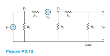
Find the power delivered to the load resistor
Want to see the full answer?
Check out a sample textbook solution
Chapter 3 Solutions
Principles and Applications of Electrical Engineering


- I need to figure out how to make an oscilliscope sketch from the VDC and VAC values.arrow_forwardDraw the equation by using Hand not Ai then solve using double integral please i need expert answerarrow_forwardcalculete all the parameters (g11/g12/g21/g22 and r11/r12/r21/r22) for the representations: voltage controlled and current controlled.voltage controlledi1=g11v1+g12v2i2=g21v1+g22v2current controlledv1=r11i1+r22i2v2=r21i1+r22i2arrow_forward
- Don't use ai to answer I will report you answerarrow_forwardcalculate the parameters (h11/h12/h21/h22) for hybrid 2 and hybrid 1 HYBRID2 i1=h11v1+h12i2 v2=h21v1+h22i2HYBRID 1v1 = h11i1 + h12v2i2 = h21i1 + h22v2arrow_forwardDescribe the flow control and load sharing features implemented in the MTP3 protocol of SS7. Explain the use of the SLS field and discuss SS7 network structure. Explain the error control mechanisms used in SS7, including preventive cyclic retransmission. Draw a diagram for the protocol model of SS7 and explain the function of each part. List the four classes of SCCP service which are available and explain one briefly. Describe the advantages and disadvantages of common channel signalling. Describe in detail the function of MTP layer 1, 2 and 3. Show the structure of message signal units (MSUS) and describe the fields used. Describe the call control procedures used in DSSI to set up and release a connection. Use a diagram to show the signalling message flows. Give details of three examples of supplementary services provided by the ISDN user part of SS7. Describe a service provided by the transaction capabilities application part. Describe the subscriber line signalling methods used for…arrow_forward
- I need to know the derivative of the blocking probability of TSSST switcharrow_forwardDraw the equation USE BY HANarrow_forwardProblem a. (i) Sketch the ideal power curve of the turbine with the following characteristics: • rated speed is 14 m/s ⚫rated power is 1.25 MW ⚫ cut-in speed is 5 m/s ⚫furling or cut-out speed is 20 m/s (ii) Given part (i), calculate the energy produced in one day if the wind blows continuously between 15 and 20 m/s all day (iii) Can the energy produced in one year be determined if you are told that the average wind speed is 14 m/s? Explain why.arrow_forward
- Problem b. Suppose an anemometer mounted at a height of 10 m with a 20-m/s average wind speed (i) Estimate the average wind power at a height of 10 m, assuming Rayleigh statistics and under the following weather conditions • 15°C (ii) Suppose a 1300-kW wind turbine with 60-m rotor diameter is located in those winds with speed computed in the first condition of part (i). Determine the annual energy production with a 30% wind turbine efficiency (iii) Evaluate the wind turbine capacity factorarrow_forwardQ3/Using Kirchhoff's laws to determine: (6degrees) a) The current (Irsa) b) The voltage across the Ri (V750) c) Calculate the power by each voltage source. d) Calculate the power of each resistor of the network. V3 12V V2 R1 3V R2 1250arrow_forwardQ1/For the network shown in the figure below, Use MESH analysis and find the current through (50) resistor. (6degrees) R. - 3 Ո 20 V R3 ΔΩ Rs ww 50 202 202 w R2 Ra 142arrow_forward
 Introductory Circuit Analysis (13th Edition)Electrical EngineeringISBN:9780133923605Author:Robert L. BoylestadPublisher:PEARSON
 Delmar's Standard Textbook Of ElectricityElectrical EngineeringISBN:9781337900348Author:Stephen L. HermanPublisher:Cengage Learning
 Programmable Logic ControllersElectrical EngineeringISBN:9780073373843Author:Frank D. PetruzellaPublisher:McGraw-Hill Education
 Fundamentals of Electric CircuitsElectrical EngineeringISBN:9780078028229Author:Charles K Alexander, Matthew SadikuPublisher:McGraw-Hill Education
 Electric Circuits. (11th Edition)Electrical EngineeringISBN:9780134746968Author:James W. Nilsson, Susan RiedelPublisher:PEARSON
 Engineering ElectromagneticsElectrical EngineeringISBN:9780078028151Author:Hayt, William H. (william Hart), Jr, BUCK, John A.Publisher:Mcgraw-hill Education,