
Principles and Applications of Electrical Engineering
6th Edition
ISBN: 9780073529592
Author: Giorgio Rizzoni Professor of Mechanical Engineering, James A. Kearns Dr.
Publisher: McGraw-Hill Education
expand_more
expand_more
format_list_bulleted
Concept explainers
Videos
Textbook Question
Chapter 3, Problem 3.18HP
Using mesh analysis. Find the voltage V across the current source in Figure P3.18.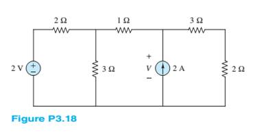
Expert Solution & Answer
Want to see the full answer?
Check out a sample textbook solution
Students have asked these similar questions
Can you please provide an explanation and working. The solution is provided.
please show working and an explanation. The ans is 20.68 ms.
A 400V,50Hz,Y-connected, 4-pole,three-phase wound rotor induction motor, the rotor circuit is Y-
connected with R2=0.1, X2= 0.8 Q/ph .The measured e.m.f between two slip rings at 1440 rpm is
165 V. If the total stator losses are 650 W,find:airgap power, rotor copper loss, input power, developed
(or gross) mechanical power, output power, efficiency, if friction and windage losses are 377W?
Chapter 3 Solutions
Principles and Applications of Electrical Engineering
Ch. 3 - Use node voltage analysis to find the voltages V1...Ch. 3 - Use node voltage analysis to find the voltages V1...Ch. 3 - Using node voltage analysis in the circuit of...Ch. 3 - Using node voltage analysis in the circuit of...Ch. 3 - In the circuit shown in Figure P3.5, the mesh...Ch. 3 - In the circuit shown in Figure P3.5, the source...Ch. 3 - Use nodal analysis in the circuit of Figure P3.7...Ch. 3 - Use mesh analysis in the circuit of Figure P3.7 to...Ch. 3 - Use nodal analysis in the circuit of Figure P3.9...Ch. 3 - Use nodal analysis in the circuit of Figure P3.10...
Ch. 3 - Use nodal analysis in the circuit of Figure P3.11...Ch. 3 - Find the power delivered to the load resistor R0...Ch. 3 - For the circuit of Figure P3.13, write the nodee...Ch. 3 - Using mesh analysis, find the currents i1 and i2...Ch. 3 - Using mesh analysis, find the currents i1 and i2...Ch. 3 - Using mesh analysis, find the voltage v across the...Ch. 3 - Using mesh analysis, find the currents I1,I2 and...Ch. 3 - Using mesh analysis. Find the voltage V across the...Ch. 3 - Prob. 3.19HPCh. 3 - For the circuit of Figure P3.20, use mesh analysis...Ch. 3 - In the circuit in Figure P3.21, assume the source...Ch. 3 - For the circuit of Figure P3.22 determine: a. The...Ch. 3 - Figure P3.23 represents a temperature measurement...Ch. 3 - Use nodal analysis on the circuit in Figure P3.24...Ch. 3 - Use mesh analysis to find the mesh currents in...Ch. 3 - Use mesh analysis to find the mesh currents in...Ch. 3 - Use mesh analysis to find the currents in Figure...Ch. 3 - Use mesh analysis to find V4 in Figure P3.28. Let...Ch. 3 - Use mesh analysis to find mesh currents in Figure...Ch. 3 - Use mesh analysis to find the current i in Figure...Ch. 3 - Use mesh analysis to find the voltage gain...Ch. 3 - Use nodal analysis to find node voltages V1,V2,...Ch. 3 - Use mesh analysis to find the currents through...Ch. 3 - Prob. 3.34HPCh. 3 - Prob. 3.35HPCh. 3 - Using the data of Problem 3.35 and Figure P3.35,...Ch. 3 - Prob. 3.37HPCh. 3 - Prob. 3.38HPCh. 3 - Use nodal analysis in the circuit of Figure P3.39...Ch. 3 - Prob. 3.40HPCh. 3 - Refer to Figure P3.10 and use the principle of...Ch. 3 - Use the principle of superposition to determine...Ch. 3 - Refer to Figure P3.43 and use the principle of...Ch. 3 - Refer to Figure P3.44 and use the principle of...Ch. 3 - Refer to Figure P3.44 and use the principle of...Ch. 3 - Prob. 3.46HPCh. 3 - Use the principle of super position to determine...Ch. 3 - Prob. 3.48HPCh. 3 - Use the principle of super position to determine...Ch. 3 - Use the principle of superposition to determine...Ch. 3 - Find the Thé venin equivalent of the network...Ch. 3 - Find the Thé venin equivalent of the network seen...Ch. 3 - Find the Norton equivalent of the network seen by...Ch. 3 - Find the Norton equivalent of the network between...Ch. 3 - Find the Thé venin equivalent of the network seen...Ch. 3 - Prob. 3.56HPCh. 3 - Find the Thé venin equivalent of the network seen...Ch. 3 - Find the Thé venin equivalent network seen by...Ch. 3 - Prob. 3.59HPCh. 3 - Prob. 3.60HPCh. 3 - Prob. 3.61HPCh. 3 - Find the Thé venin equivalent resistance seen...Ch. 3 - Find the Thé venin equivalent resistance seen by...Ch. 3 - Find the Thé venin equivalent network seen from...Ch. 3 - Find the Thé’cnin equivalent resistance seen by R3...Ch. 3 - Find the Norton equivalent of the network seen by...Ch. 3 - Find the Norton equivalent of the network seen by...Ch. 3 - Prob. 3.68HPCh. 3 - Find the Norton equivalent network between...Ch. 3 - Prob. 3.70HPCh. 3 - Prob. 3.71HPCh. 3 - Prob. 3.72HPCh. 3 - The Thé venin equivalent network seen by a load Ro...Ch. 3 - The Thévenin equivalent network seen by a load Ro...Ch. 3 - Prob. 3.75HPCh. 3 - Prob. 3.76HPCh. 3 - Many practical circuit elements are non-linear;...Ch. 3 - Prob. 3.78HPCh. 3 - The non-linear diode in Figure P3.79 has the i-v...Ch. 3 - Prob. 3.80HPCh. 3 - The non-linear device D in Figure P3.81 has the...Ch. 3 - Prob. 3.82HPCh. 3 - The so-called forward-bias i-v relationship for a...
Knowledge Booster


Learn more about
Need a deep-dive on the concept behind this application? Look no further. Learn more about this topic, electrical-engineering and related others by exploring similar questions and additional content below.Similar questions
- consider the circuit below. Assume it uses ideal diodes with the details specified above. the left side of the circuit is basically a wheatstone bridge, hooked to the right side, which is a differential op amp. a) what is the voltage between junctions "A" and "B" if R2 is 201 ohms? b) what are the minimum and maximum values of R2 can be without the op amp hitting saturation?remember that for the diodes to be ideal you they have to have a turn on voltage of 0.6 volts.arrow_forwardThe capacitors in the circuit shown below have no energy stored in them and then switch “S1” closes at time t=0. Assume the ideal op amp does not saturate. As stated above assume the diodes are ideal with parameters specified above. Diodes are at 0.6 Volts Show the derivations of the mathematical equations for v(t) at Locations A and B for t≥ 0arrow_forwardPhase (deg) Magnitude (dB) -20 -40 -60 -80 -100 ° -90 -180 -270 10-1 (i) ° Problem 5 Consider a unity (negative) feedback system with a proportional controller. The Bode plot of the plant transfer function G(s) is given as below. System: sys Frequency (rad/s): 1 Magnitude (dB): 13.9 System: sys Frequency (rad/s): 14.9 Magnitude (dB): 6.58 System: sys Frequency (rad/s): 1 Phase (deg): -9.76 10° System: sys Frequency (rad/s): 25.6 Magnitude (dB): -0.0703 System: sys Frequency (rad/s): 41.3 Magnitude (dB): -8.06 System: sys Frequency (rad/s): 200 Magnitude (dB): -44.4 System: sys Frequency (rad/s): 14.9 Phase (deg): -110 System: sys Frequency (rad/s): 25.6 Phase (deg): -148 System: sys Frequency (rad/s): 41.3 Phase (deg): -180 System: sys Frequency (rad/s): 200 Phase (deg): -247 101 Frequency (rad/s) 102 Find the gain crossover frequency, phase crossover frequency, gain margin and phase margin of the system. Is the closed-loop system stable? (ii) What is the steady-state error of the…arrow_forward
- Problem 1 Consider the following system. In the figure, y(t) denotes the voltage across the capacitor. u(t) 1+ R W L + 0000 y(t) C Y(s) (i) Find the transfer function H(s): = of the system. U(s) Now suppose, R 10 KQ, L = 0.5 mH and C = 10 μF. (ii) Find the poles and zeros. Is the system BIBO stable? (iii) Compute settling time, rise time, peak time and % overshoot of the step response of the system. What the steady-state output for unit step input?arrow_forwardA 3-phase, 52 H.P, 50 Hz, 6-Pole, Y- connected induction motor runs at a speed of 980 rpm.The motor is supplied from 380 V mains and it takes a rated current of 80 A at 0.8 p.f. If the total stator losses are 1.7 kW, determine: the air-gap power, rotor copper loss, friction and windage losses?arrow_forwardelectric plants do hand writingarrow_forward
- please solve quickly. thank you!arrow_forwardPlease show all stepsarrow_forward12-3) PDF, mean, & variance A random variable has the PDF shown in the figure. a) Find the numerical value of the parameter K. b) Write the numerical expression for the PDF. c) Find the probability that the random variable is negative. d) Find the mean of x, the expected value of x², and the variance of x. K Px(x) 3 Xarrow_forward
arrow_back_ios
SEE MORE QUESTIONS
arrow_forward_ios
Recommended textbooks for you
 Introductory Circuit Analysis (13th Edition)Electrical EngineeringISBN:9780133923605Author:Robert L. BoylestadPublisher:PEARSON
 Delmar's Standard Textbook Of ElectricityElectrical EngineeringISBN:9781337900348Author:Stephen L. HermanPublisher:Cengage Learning
 Programmable Logic ControllersElectrical EngineeringISBN:9780073373843Author:Frank D. PetruzellaPublisher:McGraw-Hill Education
 Fundamentals of Electric CircuitsElectrical EngineeringISBN:9780078028229Author:Charles K Alexander, Matthew SadikuPublisher:McGraw-Hill Education
 Electric Circuits. (11th Edition)Electrical EngineeringISBN:9780134746968Author:James W. Nilsson, Susan RiedelPublisher:PEARSON
 Engineering ElectromagneticsElectrical EngineeringISBN:9780078028151Author:Hayt, William H. (william Hart), Jr, BUCK, John A.Publisher:Mcgraw-hill Education,
Introductory Circuit Analysis (13th Edition)
Electrical Engineering
ISBN:9780133923605
Author:Robert L. Boylestad
Publisher:PEARSON
Delmar's Standard Textbook Of Electricity
Electrical Engineering
ISBN:9781337900348
Author:Stephen L. Herman
Publisher:Cengage Learning
Programmable Logic Controllers
Electrical Engineering
ISBN:9780073373843
Author:Frank D. Petruzella
Publisher:McGraw-Hill Education
Fundamentals of Electric Circuits
Electrical Engineering
ISBN:9780078028229
Author:Charles K Alexander, Matthew Sadiku
Publisher:McGraw-Hill Education
Electric Circuits. (11th Edition)
Electrical Engineering
ISBN:9780134746968
Author:James W. Nilsson, Susan Riedel
Publisher:PEARSON
Engineering Electromagnetics
Electrical Engineering
ISBN:9780078028151
Author:Hayt, William H. (william Hart), Jr, BUCK, John A.
Publisher:Mcgraw-hill Education,
Current Divider Rule; Author: Neso Academy;https://www.youtube.com/watch?v=hRU1mKWUehY;License: Standard YouTube License, CC-BY