
Concept explainers
Videos
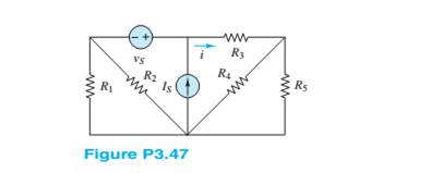
Use the principle of super position to determine the current i and
Want to see the full answer?
Check out a sample textbook solution
Chapter 3 Solutions
Principles and Applications of Electrical Engineering


- An antenna with a radiation impedance of 75+j10 ohm, with 10 ohm loss resistance, is connected to a generator with open-circuit voltage of 12 v and an internal impedance of 20 ohms via a 2/4-long transmission line with characteristic impedance of 75 ohms. (a) Draw the equivalent circuit (b) Determine the power supplied by the generator. (c) Determine the power radiated by the antenna. (d) Determine the reflection coefficient at the antenna terminals.arrow_forwardcircuit analysis using superposition what is value of iarrow_forwardTwo X-band 8.2-12.4 GHz rectangular horns, with aperture dimensions of 5.5 cm and 7.4 cm and each with a directivity of 16.3 dB (over isotropic at 10 GHz), are used as transmitting and receiving antennas. Assuming that the input power is 200 mW, the VSWR of each is 1.1. The conduction-dielectric efficiency is 100%, and the antennas are polarization-matched, find the maximum received power when the horns are separated in air by 5 m.arrow_forward
- The normalized radiation intensity of an antenna is rotationally symmetric in 4, and it is represented by 1 0°≤8 <30° 0.5 30° ≤ 0 < 60° U = 0.1 60° ≤ 0 < 90° 90° ≤ 0 ≤ 180° a) Determine the directivity (above isotropic) of an antenna in dB? b) Determine the directivity (above an infinitesimal dipole) of an antenna in dB?arrow_forwardA resonant lossless 2/2 dipole antenna, having a directivity of 2.156 dB at frequency of 9 MHz, has input impedance 73 £2 and is connected to a lossless 73 2 transmission line. A wave, having the same polarization as the antenna, is incident upon the antenna with a power density of 5 W/m². Find the received power available at the end of the transmission line.arrow_forward"Detail the solution to the question with an explanation of the integration." The normalized radiation intensity is given by: 1 0≤0≤30 U(0,) cos(0) 30 ≤0≤90 0.866 0 90 ≤0≤180 Determine the maximum directivity, HPBWarrow_forward
- Don't use ai to answer I will report you answer.arrow_forward"Detail the solution to the question with an explanation of the integration." A diploe with a total loss resistance of 12, is connected to generator whose internal impedance is 50+j25, the peak voltage of generator is 2 V and the impedance of the dipole excluding the loss resistance is 73+j42.5. All antenna and generator are connected via 50-92 2/4 long lossless transmission line. (a) Draw the equivalent circuit (b) Determine the power supplied by the generator (c) Determine the power radiated by the antennaarrow_forwardcircuit analysis find ia using mesh analysisarrow_forward
- cicuit analysisfind the power transfered to circuit by 4A currentarrow_forward"Detail the solution to the question with an explanation of the integration." The normalized far-zone power pattern of an antenna is given by for 0≤0≤ and 0≤≤/2,3/2≤≤2, U(0,0)=sine (cos0)2 elsewhere Find the directivity using the exact expression, HPBW in both azimuth and elevationarrow_forwardcircuit analysis using source transform find v?how much power does a 120v source deliver to the circuit?arrow_forward
 Introductory Circuit Analysis (13th Edition)Electrical EngineeringISBN:9780133923605Author:Robert L. BoylestadPublisher:PEARSON
 Delmar's Standard Textbook Of ElectricityElectrical EngineeringISBN:9781337900348Author:Stephen L. HermanPublisher:Cengage Learning
 Programmable Logic ControllersElectrical EngineeringISBN:9780073373843Author:Frank D. PetruzellaPublisher:McGraw-Hill Education
 Fundamentals of Electric CircuitsElectrical EngineeringISBN:9780078028229Author:Charles K Alexander, Matthew SadikuPublisher:McGraw-Hill Education
 Electric Circuits. (11th Edition)Electrical EngineeringISBN:9780134746968Author:James W. Nilsson, Susan RiedelPublisher:PEARSON
 Engineering ElectromagneticsElectrical EngineeringISBN:9780078028151Author:Hayt, William H. (william Hart), Jr, BUCK, John A.Publisher:Mcgraw-hill Education,