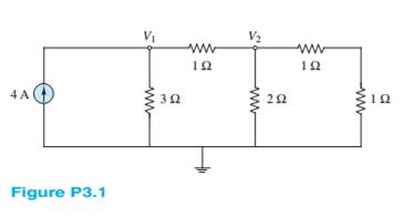
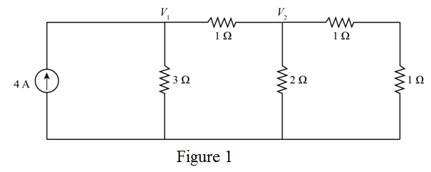
Problem 3.1HP: Use node voltage analysis to find the voltages V1 and V2 for the circuit of Figure P3.1. Problem 3.2HP: Use node voltage analysis to find the voltages V1 and V2 for the circuit of Figure P3.2. Problem 3.3HP: Using node voltage analysis in the circuit of FigureP3.3, find the voltage v across the 0.25-... Problem 3.4HP: Using node voltage analysis in the circuit of Figure P3.4. find the current i through the voltage... Problem 3.5HP: In the circuit shown in Figure P3.5, the mesh currents are I1=5AI2=3AI3=7A Determine the branch... Problem 3.6HP: In the circuit shown in Figure P3.5, the source and node voltages are Vs1=Vs2=110VVA=103VVB=107V... Problem 3.7HP: Use nodal analysis in the circuit of Figure P3.7 to find Va . Let R1=12,R2=6,R3=10,V1=4V,V2=1V . Problem 3.8HP: Use mesh analysis in the circuit of Figure P3.7 to find Va . Let R1=12,R2=6,R3=10,V1=4V,V2=1V . Problem 3.9HP: Use nodal analysis in the circuit of Figure P3.9 to find v1,v2, and v3 . Let... Problem 3.10HP: Use nodal analysis in the circuit of Figure P3.10 to find the voltages at nodes A, B, and C. Let... Problem 3.11HP: Use nodal analysis in the circuit of Figure P3.11 to find Va and Vb . Let... Problem 3.12HP: Find the power delivered to the load resistor R0 for the circuit of Figure P3.12, using node voltage... Problem 3.13HP: For the circuit of Figure P3.13, write the nodee quations necessary to find voltages V1,V2, and V3... Problem 3.14HP: Using mesh analysis, find the currents i1 and i2 for the circuit of Figure P3.14. Problem 3.15HP: Using mesh analysis, find the currents i1 and i2 and the voltage across the upper 10- resistor in... Problem 3.16HP: Using mesh analysis, find the voltage v across the 3- resistor in the circuit of Figure P3.16. Problem 3.17HP: Using mesh analysis, find the currents I1,I2 and I3 in the circuit of Figure P3.17 (assume polarity... Problem 3.18HP: Using mesh analysis. Find the voltage V across the current source in Figure P3.18. Problem 3.19HP Problem 3.20HP: For the circuit of Figure P3.20, use mesh analysis to find four equations in the four mesh... Problem 3.21HP: In the circuit in Figure P3.21, assume the source voltage and source current and all resistances are... Problem 3.22HP: For the circuit of Figure P3.22 determine: a. The most efficient way to solve for the voltage a... Problem 3.23HP: Figure P3.23 represents a temperature measurement system, where temperature T is linear lyrelated to... Problem 3.24HP: Use nodal analysis on the circuit in Figure P3.24 todetermine the voltage V4 . Note that one source... Problem 3.25HP: Use mesh analysis to find the mesh currents in Figure P3.25.Let R1=10,R2=5,V1=2V,V2=1V,Is=2A . Problem 3.26HP: Use mesh analysis to find the mesh currents in Figure P3.26. Let R1=6,R2=3,R3=3,V1=4V,V2=1V,V3=2V . Problem 3.27HP: Use mesh analysis to find the currents in Figure P3.27. Let... Problem 3.28HP: Use mesh analysis to find V4 in Figure P3.28. Let R2=6,R3=3,R4=3,R5=3,vs=4V,is=2A . Problem 3.29HP: Use mesh analysis to find mesh currents in Figure P3.29. Let... Problem 3.30HP: Use mesh analysis to find the current i in Figure P3.30. Assume is=2A . Problem 3.31HP: Use mesh analysis to find the voltage gain Gv=v2/vs in Figure P3.31. Problem 3.32HP: Use nodal analysis to find node voltages V1,V2, and V3 , in figure P3.32.Let... Problem 3.33HP: Use mesh analysis to find the currents through every branch in Figure P3.33. Let... Problem 3.34HP Problem 3.35HP Problem 3.36HP: Using the data of Problem 3.35 and Figure P3.35, a. Determine the number of meshes. b. Compute the... Problem 3.37HP Problem 3.38HP Problem 3.39HP: Use nodal analysis in the circuit of Figure P3.39 tofind the three indicated node voltages and the... Problem 3.40HP Problem 3.41HP: Refer to Figure P3.10 and use the principle of super position to find the voltages at nodes A,B, and... Problem 3.42HP: Use the principle of superposition to determine thevoltage v across R2 in Figure P3.42.... Problem 3.43HP: Refer to Figure P3.43 and use the principle of super position to determine the component of the... Problem 3.44HP: Refer to Figure P3.44 and use the principle of super position to determine the current i through R4... Problem 3.45HP: Refer to Figure P3.44 and use the principle of super position to determine the current i through R4... Problem 3.46HP Problem 3.47HP: Use the principle of super position to determine the current i and R3 in Figure P3.47. Let... Problem 3.48HP Problem 3.49HP: Use the principle of super position to determine the power P supplied by Vs in Figure P3.49. Let... Problem 3.50HP: Use the principle of superposition to determine the current io supplied by R1 in Figure P3.50. Let... Problem 3.51HP: Find the Thé venin equivalent of the network seenby the 3- resistor in Figure P3.5 1. Problem 3.52HP: Find the Thé venin equivalent of the network seen by the 3- resistor in Figure P3.52. U it and... Problem 3.53HP: Find the Norton equivalent of the network seen by R2 in Figure P3.53. Use it and current division to... Problem 3.54HP: Find the Norton equivalent of the network between nodes a andb in Figure P3.54. Problem 3.55HP: Find the Thé venin equivalent of the network seen by R in Figure P3.55, and use the result to... Problem 3.56HP Problem 3.57HP: Find the Thé venin equivalent of the network seen by the load Ro in Figure P3.57. Problem 3.58HP: Find the Thé venin equivalent network seen by theload Ro in Figure P3.58, where R1=10,R2=20,Rg=0.1,... Problem 3.59HP Problem 3.60HP Problem 3.61HP Problem 3.62HP: Find the Thé venin equivalent resistance seen byresistor R3 in the circuit of Figure P3.5. Compute... Problem 3.63HP: Find the Thé venin equivalent resistance seen by resistor R4 in the circuit of Figure P3.10. Compute... Problem 3.64HP: Find the Thé venin equivalent network seen from node a tob in Figure P3.64. Let... Problem 3.65HP: Find the Thé’cnin equivalent resistance seen by R3 in Figure P3.23. Compute the Thévenin... Problem 3.66HP: Find the Norton equivalent of the network seen by R5 in Figure P3.66. Use it and current division to... Problem 3.67HP: Find the Norton equivalent of the network seen by R3 in Figure P3.66. Use it to determine the power... Problem 3.68HP Problem 3.69HP: Find the Norton equivalent network between terminals a and b in Figure P3.69. Let... Problem 3.70HP Problem 3.71HP Problem 3.72HP Problem 3.73HP: The Thé venin equivalent network seen by a load Ro is depicted in Figure P3.73. Assume VT=10V,RT=2 ,... Problem 3.74HP: The Thévenin equivalent network seen by a load Ro is depicted in Figure P3.73. Assume VT=25V,RT=100... Problem 3.75HP Problem 3.76HP Problem 3.77HP: Many practical circuit elements are non-linear; however, it is usually possible to linearize the V-I... Problem 3.78HP Problem 3.79HP: The non-linear diode in Figure P3.79 has the i-v character is tic shown. Assume: VS=VTH=1.5VR=Req=60... Problem 3.80HP Problem 3.81HP: The non-linear device D in Figure P3.81 has the following transcendental i-v character is tic:... Problem 3.82HP Problem 3.83HP: The so-called forward-bias i-v relationship for a silicon diode is: iD=ISAT[e( v D/ V thermal)1]... format_list_bulleted


 Introductory Circuit Analysis (13th Edition)Electrical EngineeringISBN:9780133923605Author:Robert L. BoylestadPublisher:PEARSON
 Delmar's Standard Textbook Of ElectricityElectrical EngineeringISBN:9781337900348Author:Stephen L. HermanPublisher:Cengage Learning
 Programmable Logic ControllersElectrical EngineeringISBN:9780073373843Author:Frank D. PetruzellaPublisher:McGraw-Hill Education
 Fundamentals of Electric CircuitsElectrical EngineeringISBN:9780078028229Author:Charles K Alexander, Matthew SadikuPublisher:McGraw-Hill Education
 Electric Circuits. (11th Edition)Electrical EngineeringISBN:9780134746968Author:James W. Nilsson, Susan RiedelPublisher:PEARSON
 Engineering ElectromagneticsElectrical EngineeringISBN:9780078028151Author:Hayt, William H. (william Hart), Jr, BUCK, John A.Publisher:Mcgraw-hill Education,