
Principles and Applications of Electrical Engineering
6th Edition
ISBN: 9780073529592
Author: Giorgio Rizzoni Professor of Mechanical Engineering, James A. Kearns Dr.
Publisher: McGraw-Hill Education
expand_more
expand_more
format_list_bulleted
Concept explainers
Videos
Textbook Question
Chapter 3, Problem 3.20HP
For the circuit of Figure P3.20, use mesh analysis to find four equations in the four mesh currents.Collect coefficients and solve for the mesh currents.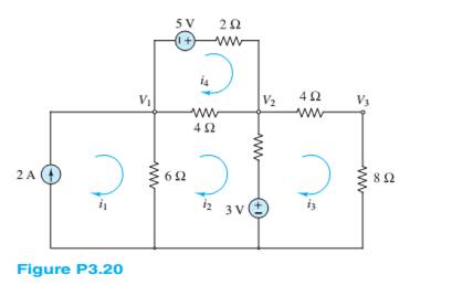
Expert Solution & Answer
Want to see the full answer?
Check out a sample textbook solution
Students have asked these similar questions
Not use ai please
Help on this equation system?
Transmitting and receiving antennas operating at 1 GHz with gains of 20 and 15 dB,
respectively, are separated by a distance of 1 km. Find the power delivered to the load
when the input power is 150 W. Assume the PLF = 1.
Chapter 3 Solutions
Principles and Applications of Electrical Engineering
Ch. 3 - Use node voltage analysis to find the voltages V1...Ch. 3 - Use node voltage analysis to find the voltages V1...Ch. 3 - Using node voltage analysis in the circuit of...Ch. 3 - Using node voltage analysis in the circuit of...Ch. 3 - In the circuit shown in Figure P3.5, the mesh...Ch. 3 - In the circuit shown in Figure P3.5, the source...Ch. 3 - Use nodal analysis in the circuit of Figure P3.7...Ch. 3 - Use mesh analysis in the circuit of Figure P3.7 to...Ch. 3 - Use nodal analysis in the circuit of Figure P3.9...Ch. 3 - Use nodal analysis in the circuit of Figure P3.10...
Ch. 3 - Use nodal analysis in the circuit of Figure P3.11...Ch. 3 - Find the power delivered to the load resistor R0...Ch. 3 - For the circuit of Figure P3.13, write the nodee...Ch. 3 - Using mesh analysis, find the currents i1 and i2...Ch. 3 - Using mesh analysis, find the currents i1 and i2...Ch. 3 - Using mesh analysis, find the voltage v across the...Ch. 3 - Using mesh analysis, find the currents I1,I2 and...Ch. 3 - Using mesh analysis. Find the voltage V across the...Ch. 3 - Prob. 3.19HPCh. 3 - For the circuit of Figure P3.20, use mesh analysis...Ch. 3 - In the circuit in Figure P3.21, assume the source...Ch. 3 - For the circuit of Figure P3.22 determine: a. The...Ch. 3 - Figure P3.23 represents a temperature measurement...Ch. 3 - Use nodal analysis on the circuit in Figure P3.24...Ch. 3 - Use mesh analysis to find the mesh currents in...Ch. 3 - Use mesh analysis to find the mesh currents in...Ch. 3 - Use mesh analysis to find the currents in Figure...Ch. 3 - Use mesh analysis to find V4 in Figure P3.28. Let...Ch. 3 - Use mesh analysis to find mesh currents in Figure...Ch. 3 - Use mesh analysis to find the current i in Figure...Ch. 3 - Use mesh analysis to find the voltage gain...Ch. 3 - Use nodal analysis to find node voltages V1,V2,...Ch. 3 - Use mesh analysis to find the currents through...Ch. 3 - Prob. 3.34HPCh. 3 - Prob. 3.35HPCh. 3 - Using the data of Problem 3.35 and Figure P3.35,...Ch. 3 - Prob. 3.37HPCh. 3 - Prob. 3.38HPCh. 3 - Use nodal analysis in the circuit of Figure P3.39...Ch. 3 - Prob. 3.40HPCh. 3 - Refer to Figure P3.10 and use the principle of...Ch. 3 - Use the principle of superposition to determine...Ch. 3 - Refer to Figure P3.43 and use the principle of...Ch. 3 - Refer to Figure P3.44 and use the principle of...Ch. 3 - Refer to Figure P3.44 and use the principle of...Ch. 3 - Prob. 3.46HPCh. 3 - Use the principle of super position to determine...Ch. 3 - Prob. 3.48HPCh. 3 - Use the principle of super position to determine...Ch. 3 - Use the principle of superposition to determine...Ch. 3 - Find the Thé venin equivalent of the network...Ch. 3 - Find the Thé venin equivalent of the network seen...Ch. 3 - Find the Norton equivalent of the network seen by...Ch. 3 - Find the Norton equivalent of the network between...Ch. 3 - Find the Thé venin equivalent of the network seen...Ch. 3 - Prob. 3.56HPCh. 3 - Find the Thé venin equivalent of the network seen...Ch. 3 - Find the Thé venin equivalent network seen by...Ch. 3 - Prob. 3.59HPCh. 3 - Prob. 3.60HPCh. 3 - Prob. 3.61HPCh. 3 - Find the Thé venin equivalent resistance seen...Ch. 3 - Find the Thé venin equivalent resistance seen by...Ch. 3 - Find the Thé venin equivalent network seen from...Ch. 3 - Find the Thé’cnin equivalent resistance seen by R3...Ch. 3 - Find the Norton equivalent of the network seen by...Ch. 3 - Find the Norton equivalent of the network seen by...Ch. 3 - Prob. 3.68HPCh. 3 - Find the Norton equivalent network between...Ch. 3 - Prob. 3.70HPCh. 3 - Prob. 3.71HPCh. 3 - Prob. 3.72HPCh. 3 - The Thé venin equivalent network seen by a load Ro...Ch. 3 - The Thévenin equivalent network seen by a load Ro...Ch. 3 - Prob. 3.75HPCh. 3 - Prob. 3.76HPCh. 3 - Many practical circuit elements are non-linear;...Ch. 3 - Prob. 3.78HPCh. 3 - The non-linear diode in Figure P3.79 has the i-v...Ch. 3 - Prob. 3.80HPCh. 3 - The non-linear device D in Figure P3.81 has the...Ch. 3 - Prob. 3.82HPCh. 3 - The so-called forward-bias i-v relationship for a...
Knowledge Booster


Learn more about
Need a deep-dive on the concept behind this application? Look no further. Learn more about this topic, electrical-engineering and related others by exploring similar questions and additional content below.Similar questions
- Calculate the voltage gain and I/O impedance of circuits shown in Fig. 1. Assume (60 points- each section 20 points) J Vina кат Vb J Vina кат VCC VCC VCC Vino - Vout - Vout Rs w Q2 Q2 (c) (b) Q2 = (a) - Voutarrow_forwardNot use ai please letarrow_forwardUse PSpice to create the circuit and show the circuit along with simulation results. Also please explicitly answer the question (i.e. have the answer make sense and not in parts where there is no final answer.)arrow_forward
- Problem 5 Plot the impulse response of the system shown below. Hint: This is done graphically with 4 convolutions. x[n] D y[n]< D D D D D D D D D D Darrow_forwardUse PSpice to create the circuit. Also please explicitly answer whether the load line intersects the -0.7 line at the computed point.arrow_forwardIn class, we wrote on the blackboard a byte addressable memory where each element was 2 nibbles: For example: Main memory A Address Offset Data Data Data Data Data Data Data Data Data Data Data Data Data Data Data Data 0 1 2 3 4 5 6 0 Ox10 0x00 0x02 0x2B Ox4F 0x00 0x00 0x00 0x11 0x12 0x20 0x10 0x10 0x00 OxFF Ox3E DxDD 0x00 0x00 0x00 0x00 0x00 0x00 0x00 7 0x1C 0x00 8 9 A 0x00 0x00 0x01 0x00 0x00 0x01 0x00 0x00 0x01 B с D E 0x00 0x05 0x04 0x03 0x02 0x00 Ox3D 0x00 0x1C Ox2F 0x00 Ox1F OxFF 0x03 0x02 F What is the contents of address 0x1C in main memory A for a 32 bit machine using Big Endian format? What is the contents of address 0x1C in main memory A for a 16 bit machine using Little Endian format? What is the contents of the indirect address at 0x04 in main memory A for a Big Endian 32 bit machine ((0x4))? What is the contents of 4(0x10) in main memory A for a 16 bit Little Endian machine? What is the contents of the address 16(0xC) for a 64 bit Little Endian machine?arrow_forward
- Problem 4 Consider the system shown below where h₁[n] = {2,1,2} and h₂[n] = (n+1) u[n] (− means subtraction). h₂[n] x [n]- h₁[n] бел-27- h₂[n] y[n] (a) Determine the impulse response of the system and plot it for n = -3,...,6. (b) Determine graphically the response of the system to the following input. x[n] 2 4 5arrow_forwardNot use ai pleasearrow_forwardDesign a self-biased JFET circuit (Fig. 6) assuming VGS(0) = -1.3 and ipss= 20 mA. We require a VGS = -0.7. Assume a supply voltage of 15 volts. Draw the load line for this circuit using Fig. 4b once you have selected the appropriate values for the components. Does the load line intersect the VGS = -0.7 volt line at the computed in point? RD. RG Rs 12 20nA GS = -1.3 VGS 10nA Fig. 6. Circuit for Examples 2 &3. 50 100 150 200 □ ID(J1) UDS Fig. 4b. The IV characteristics of an n-channel JFET (J113). The plots are for VGs increments of 0.05 volts. VGS(0) -1.3. The yellow and blue load lines are for examples 2 &3, respectively.arrow_forward
arrow_back_ios
SEE MORE QUESTIONS
arrow_forward_ios
Recommended textbooks for you
 Introductory Circuit Analysis (13th Edition)Electrical EngineeringISBN:9780133923605Author:Robert L. BoylestadPublisher:PEARSON
 Delmar's Standard Textbook Of ElectricityElectrical EngineeringISBN:9781337900348Author:Stephen L. HermanPublisher:Cengage Learning
 Programmable Logic ControllersElectrical EngineeringISBN:9780073373843Author:Frank D. PetruzellaPublisher:McGraw-Hill Education
 Fundamentals of Electric CircuitsElectrical EngineeringISBN:9780078028229Author:Charles K Alexander, Matthew SadikuPublisher:McGraw-Hill Education
 Electric Circuits. (11th Edition)Electrical EngineeringISBN:9780134746968Author:James W. Nilsson, Susan RiedelPublisher:PEARSON
 Engineering ElectromagneticsElectrical EngineeringISBN:9780078028151Author:Hayt, William H. (william Hart), Jr, BUCK, John A.Publisher:Mcgraw-hill Education,
Introductory Circuit Analysis (13th Edition)
Electrical Engineering
ISBN:9780133923605
Author:Robert L. Boylestad
Publisher:PEARSON
Delmar's Standard Textbook Of Electricity
Electrical Engineering
ISBN:9781337900348
Author:Stephen L. Herman
Publisher:Cengage Learning
Programmable Logic Controllers
Electrical Engineering
ISBN:9780073373843
Author:Frank D. Petruzella
Publisher:McGraw-Hill Education
Fundamentals of Electric Circuits
Electrical Engineering
ISBN:9780078028229
Author:Charles K Alexander, Matthew Sadiku
Publisher:McGraw-Hill Education
Electric Circuits. (11th Edition)
Electrical Engineering
ISBN:9780134746968
Author:James W. Nilsson, Susan Riedel
Publisher:PEARSON
Engineering Electromagnetics
Electrical Engineering
ISBN:9780078028151
Author:Hayt, William H. (william Hart), Jr, BUCK, John A.
Publisher:Mcgraw-hill Education,
Current Divider Rule; Author: Neso Academy;https://www.youtube.com/watch?v=hRU1mKWUehY;License: Standard YouTube License, CC-BY