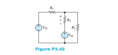
Use the principle of superposition to determine thevoltage v across

Trending nowThis is a popular solution!

Chapter 3 Solutions
Principles and Applications of Electrical Engineering
- A linear electrical load draws 11 A at a 0.72 lagging power factor./1 153. When a capacitor is connected, the line current dropped to 122 A and the power factor improved to 0.98 lagging. Supply frequency is 50 Hz. a. Let the current drawn from the source before and after introduction of the capacitor be 11 and 12 respectively. Take the source voltage as the reference and express 11 and 12 as vector quantities in polar form. b. Obtain the capacitor current, IC = 12 - 11, graphically as well as using complex number manipulation. Compare the results. c. Express the waveforms of the source current before (11(t)) and after (12(t)) introduction of the capacitor in the form Im sin(2лft + 0). Hand sketch them on the same graph. Clearly label your plots. d. Analytically solve i2(t) – i1(t) using the theories of trigonometry to obtain the capacitor current in the form, ¡C(t) = ICm sin(2πft + OC). Compare the result with the result in Part b.arrow_forwardTransmission line data:Data:• Active power of the load (P): 50 kW• Power factor of the load (PF): 0.8 (lagging)• Line-to-line voltage at the load (V_LC): 13.8 kV• Line resistance (R): 2 Ω• Line inductance (L): 0.8 H• Line capacitance (C): 0.0003 F• Required series compensation: 60% of the line impedance.• Line length: 250 kmDetermine:1. Characteristic impedance and propagation constant.2. The generalized long line constants A, B, C, D.3. Total voltage, current and power at the generating end.4. Voltage regulation.5. Parameters A, B, C, D of the compensation circuit.6. New generalized constants of the power system afterseries compensation.7. Conclusion of the results obtained.arrow_forward3.18 In a single-phase half-wave ac-dc converter, the average value of the load current is 1.78 A. If the converter is operated from a 240 V, 50 Hz supply and if the average value of the output voltage is 27% of the maximum possible value, calculate the following, assume the load to be resistive. (a) Load resistance (b) Firing angle (c) Average output voltage (d) The rms load voltage (e) The rms load current (f) DC power (g) AC power (h) Rectifier efficiency (i) Form factor (j) Ripple factorarrow_forward
- Disassemmble In another way f(t) = [sin(200πt) - cos(300πt)]2arrow_forward☑ 口 ☐ : Homework help starts here! Home | bartleby → https://www.bartleby.com Answered: Decompose using relationships 3 S(+) = 50 sin 3 (500πiz) | bartleby ASK AN EXPERT √ MATH SOLVER Decompose using relationships 3 S(+) = 50 sin 3 (500... Steps "Disassemble in another way." f(+)= 50 Sin³ (500+) Step 1 To decompose f(t)=50 Sin³ (500x+), use trigonometric indentity for Sin³ (e) Sin³ (0)- 3 Sin (e)-Sin (30) 4 Step2: Apply indentity to f(t). f(+)= 50 Sin³ (500+) = 50. 3 Sin (500+) - Sin (3*500π+) = 50. = = 12.5 4 3 Sin (500+)-Sin (1500+) 4 [3 Sin (580x+)-Sin (1500x+)] 37.5 Sin (500+)-12.5 Sin (1500π+) final decomposed form is, PM 05:2 19/12/2024 દ ))^ C W E × م اكتب هنا للبحثarrow_forward6) The principal of DIT hire you to design PBAX with 120 phones. Assuming the number of call is 3/hour/line, the average call duration is 4 minutes, and 55% of all call are made external via a T-1 trunk (24 channels) to the PSTN. Determine carried traffic and channel usage.arrow_forward
- Need a solufor number 2arrow_forwardDecompose using relationships 3 S(+) = 50 sin ³ (500πiz)arrow_forwardA linear electrical load draws I₁ A at a 0.72 lagging power factor. 11 = 153 When a capacitor is connected, the line current dropped to 122 A and the power factor improved to 0.98 lagging. Supply frequency is 50 Hz. a. Let the current drawn from the source before and after introduction of the capacitor be 1₁ and 12 respectively. Take the source voltage as the reference and express 11 and 12 as vector quantities in polar form. b. Obtain the capacitor current, Ic = I2 − I₁, graphically as well as using complex number manipulation. Compare the results. c. Express the waveforms of the source current before (i₁(t)) and after (i2(t)) introduction of the capacitor in the form Im sin(2лft + 0). Hand sketch them on the same graph. Clearly label your plots. d. Analytically solve i₂ (t) - i₁ (t) using the theories of trigonometry to obtain the capacitor current in the form, ic (t) = 1cm sin(2´ft + 0c). Compare the result with the result in Part b.arrow_forward
 Introductory Circuit Analysis (13th Edition)Electrical EngineeringISBN:9780133923605Author:Robert L. BoylestadPublisher:PEARSON
 Delmar's Standard Textbook Of ElectricityElectrical EngineeringISBN:9781337900348Author:Stephen L. HermanPublisher:Cengage Learning
 Programmable Logic ControllersElectrical EngineeringISBN:9780073373843Author:Frank D. PetruzellaPublisher:McGraw-Hill Education
 Fundamentals of Electric CircuitsElectrical EngineeringISBN:9780078028229Author:Charles K Alexander, Matthew SadikuPublisher:McGraw-Hill Education
 Electric Circuits. (11th Edition)Electrical EngineeringISBN:9780134746968Author:James W. Nilsson, Susan RiedelPublisher:PEARSON
 Engineering ElectromagneticsElectrical EngineeringISBN:9780078028151Author:Hayt, William H. (william Hart), Jr, BUCK, John A.Publisher:Mcgraw-hill Education,


