Brake or turn ? Figure 6- 44 depicts an overhead view of a car’s path as the car travels toward a wall. Assume that the driver begins to brake the car when the distance to the wall is d = 107 m, and take the car’s mass as m = 1400 kg, its initial speed as v 0 = 35 m/s, and the coefficient of static friction as µ s = 0.50. Assume that the car’s weight is distributed evenly on the four wheels, even during braking. (a) What magnitude of static friction is needed (between tires and road) to stop the car just as it reaches the wall? (b) What is the maximum possible static friction ƒ s , max ? (c) If the coefficient of kinetic friction between the (sliding) tires and the road is µ k = 0.40, at what speed will the car hit the wall? To avoid the crash, a driver could elect to turn the car so that it just barely misses the wall, as shown in the figure. (d) What magnitude of frictional force would be required to keep the car in a circular path of radius d and at the given speed v 0 , so that the car moves in a quarter circle and then parallel to the wall? (e) Is the required force less than ƒ s , max so that a circular path is possible? Figure 6-44 Problem 58.
Brake or turn ? Figure 6- 44 depicts an overhead view of a car’s path as the car travels toward a wall. Assume that the driver begins to brake the car when the distance to the wall is d = 107 m, and take the car’s mass as m = 1400 kg, its initial speed as v 0 = 35 m/s, and the coefficient of static friction as µ s = 0.50. Assume that the car’s weight is distributed evenly on the four wheels, even during braking. (a) What magnitude of static friction is needed (between tires and road) to stop the car just as it reaches the wall? (b) What is the maximum possible static friction ƒ s , max ? (c) If the coefficient of kinetic friction between the (sliding) tires and the road is µ k = 0.40, at what speed will the car hit the wall? To avoid the crash, a driver could elect to turn the car so that it just barely misses the wall, as shown in the figure. (d) What magnitude of frictional force would be required to keep the car in a circular path of radius d and at the given speed v 0 , so that the car moves in a quarter circle and then parallel to the wall? (e) Is the required force less than ƒ s , max so that a circular path is possible? Figure 6-44 Problem 58.
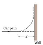
Brake or turn? Figure 6- 44 depicts an overhead view of a car’s path as the car travels toward a wall. Assume that the driver begins to brake the car when the distance to the wall is d = 107 m, and take the car’s mass as m = 1400 kg, its initial speed as v0 = 35 m/s, and the coefficient of static friction as µs = 0.50. Assume that the car’s weight is distributed evenly on the four wheels, even during braking. (a) What magnitude of static friction is needed (between tires and road) to stop the car just as it reaches the wall? (b) What is the maximum possible static friction ƒs, max? (c) If the coefficient of kinetic friction between the (sliding) tires and the road is µk = 0.40, at what speed will the car hit the wall? To avoid the crash, a driver could elect to turn the car so that it just barely misses the wall, as shown in the figure. (d) What magnitude of frictional force would be required to keep the car in a circular path of radius d and at the given speed v0, so that the car moves in a quarter circle and then parallel to the wall? (e) Is the required force less than ƒs, max so that a circular path is possible?
For each of the actions depicted below, a magnet and/or metal loop moves with velocity v→ (v→ is constant and has the same magnitude in all parts). Determine whether a current is induced in the metal loop. If so, indicate the direction of the current in the loop, either clockwise or counterclockwise when seen from the right of the loop. The axis of the magnet is lined up with the center of the loop. For the action depicted in (Figure 5), indicate the direction of the induced current in the loop (clockwise, counterclockwise or zero, when seen from the right of the loop). I know that the current is clockwise, I just dont understand why. Please fully explain why it's clockwise, Thank you
A planar double pendulum consists of two point masses \[m_1 = 1.00~\mathrm{kg}, \qquad m_2 = 1.00~\mathrm{kg}\]connected by massless, rigid rods of lengths \[L_1 = 1.00~\mathrm{m}, \qquad L_2 = 1.20~\mathrm{m}.\]The upper rod is hinged to a fixed pivot; gravity acts vertically downward with\[g = 9.81~\mathrm{m\,s^{-2}}.\]Define the generalized coordinates \(\theta_1,\theta_2\) as the angles each rod makes with thedownward vertical (positive anticlockwise, measured in radians unless stated otherwise).At \(t=0\) the system is released from rest with \[\theta_1(0)=120^{\circ}, \qquad\theta_2(0)=-10^{\circ}, \qquad\dot{\theta}_1(0)=\dot{\theta}_2(0)=0 .\]Using the exact nonlinear equations of motion (no small-angle or planar-pendulumapproximations) and assuming the rods never stretch or slip, determine the angle\(\theta_2\) at the instant\[t = 10.0~\mathrm{s}.\]Give the result in degrees, in the interval \((-180^{\circ},180^{\circ}]\).
What are the expected readings of the ammeter and voltmeter for the circuit in the figure below? (R = 5.60 Ω, ΔV = 6.30 V)
ammeter
I =
College Physics: A Strategic Approach (3rd Edition)
Knowledge Booster
Learn more about
Need a deep-dive on the concept behind this application? Look no further. Learn more about this topic, physics and related others by exploring similar questions and additional content below.


 Glencoe Physics: Principles and Problems, Student...PhysicsISBN:9780078807213Author:Paul W. ZitzewitzPublisher:Glencoe/McGraw-Hill
 Physics for Scientists and Engineers: Foundations...PhysicsISBN:9781133939146Author:Katz, Debora M.Publisher:Cengage Learning
 Principles of Physics: A Calculus-Based TextPhysicsISBN:9781133104261Author:Raymond A. Serway, John W. JewettPublisher:Cengage Learning
 Classical Dynamics of Particles and SystemsPhysicsISBN:9780534408961Author:Stephen T. Thornton, Jerry B. MarionPublisher:Cengage Learning
 Physics for Scientists and Engineers, Technology ...PhysicsISBN:9781305116399Author:Raymond A. Serway, John W. JewettPublisher:Cengage Learning
 College PhysicsPhysicsISBN:9781285737027Author:Raymond A. Serway, Chris VuillePublisher:Cengage Learning