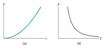
An 85.0 kg passenger is made to move along a circular path of radius r = 3.50 m in uniform circular motion. (a) Figure 6-40 a is a plot of the required magnitude F of the net centripetal force for a range of possible values of the passenger’s speed v . What is the plot’s slope at v = 8.30 m/s? (b) Figure 6-40 b is a plot of F for a range of possible values of T, the period of the motion. What is the plot’s slope at T = 2.50 s? Figure 6-40 Problem 50.
An 85.0 kg passenger is made to move along a circular path of radius r = 3.50 m in uniform circular motion. (a) Figure 6-40 a is a plot of the required magnitude F of the net centripetal force for a range of possible values of the passenger’s speed v . What is the plot’s slope at v = 8.30 m/s? (b) Figure 6-40 b is a plot of F for a range of possible values of T, the period of the motion. What is the plot’s slope at T = 2.50 s? Figure 6-40 Problem 50.
An 85.0 kg passenger is made to move along a circular path of radius r = 3.50 m in uniform circular motion. (a) Figure 6-40a is a plot of the required magnitude F of the net centripetal force for a range of possible values of the passenger’s speed v. What is the plot’s slope at v = 8.30 m/s? (b) Figure 6-40b is a plot of F for a range of possible values of T, the period of the motion. What is the plot’s slope at T = 2.50 s?
Figure 6-40 Problem 50.
Definition Definition Force on a body along the radial direction. Centripetal force is responsible for the circular motion of a body. The magnitude of centripetal force is given by F C = m v 2 r m = mass of the body in the circular motion v = tangential velocity of the body r = radius of the circular path
For each of the actions depicted below, a magnet and/or metal loop moves with velocity v→ (v→ is constant and has the same magnitude in all parts). Determine whether a current is induced in the metal loop. If so, indicate the direction of the current in the loop, either clockwise or counterclockwise when seen from the right of the loop. The axis of the magnet is lined up with the center of the loop. For the action depicted in (Figure 5), indicate the direction of the induced current in the loop (clockwise, counterclockwise or zero, when seen from the right of the loop). I know that the current is clockwise, I just dont understand why. Please fully explain why it's clockwise, Thank you
A planar double pendulum consists of two point masses \[m_1 = 1.00~\mathrm{kg}, \qquad m_2 = 1.00~\mathrm{kg}\]connected by massless, rigid rods of lengths \[L_1 = 1.00~\mathrm{m}, \qquad L_2 = 1.20~\mathrm{m}.\]The upper rod is hinged to a fixed pivot; gravity acts vertically downward with\[g = 9.81~\mathrm{m\,s^{-2}}.\]Define the generalized coordinates \(\theta_1,\theta_2\) as the angles each rod makes with thedownward vertical (positive anticlockwise, measured in radians unless stated otherwise).At \(t=0\) the system is released from rest with \[\theta_1(0)=120^{\circ}, \qquad\theta_2(0)=-10^{\circ}, \qquad\dot{\theta}_1(0)=\dot{\theta}_2(0)=0 .\]Using the exact nonlinear equations of motion (no small-angle or planar-pendulumapproximations) and assuming the rods never stretch or slip, determine the angle\(\theta_2\) at the instant\[t = 10.0~\mathrm{s}.\]Give the result in degrees, in the interval \((-180^{\circ},180^{\circ}]\).
What are the expected readings of the ammeter and voltmeter for the circuit in the figure below? (R = 5.60 Ω, ΔV = 6.30 V)
ammeter
I =
Need a deep-dive on the concept behind this application? Look no further. Learn more about this topic, physics and related others by exploring similar questions and additional content below.


 University Physics Volume 1PhysicsISBN:9781938168277Author:William Moebs, Samuel J. Ling, Jeff SannyPublisher:OpenStax - Rice University
 Classical Dynamics of Particles and SystemsPhysicsISBN:9780534408961Author:Stephen T. Thornton, Jerry B. MarionPublisher:Cengage Learning
 Physics for Scientists and Engineers: Foundations...PhysicsISBN:9781133939146Author:Katz, Debora M.Publisher:Cengage Learning
 Principles of Physics: A Calculus-Based TextPhysicsISBN:9781133104261Author:Raymond A. Serway, John W. JewettPublisher:Cengage Learning
 Glencoe Physics: Principles and Problems, Student...PhysicsISBN:9780078807213Author:Paul W. ZitzewitzPublisher:Glencoe/McGraw-Hill
 Physics for Scientists and Engineers, Technology ...PhysicsISBN:9781305116399Author:Raymond A. Serway, John W. JewettPublisher:Cengage Learning