
Concept explainers
Videos
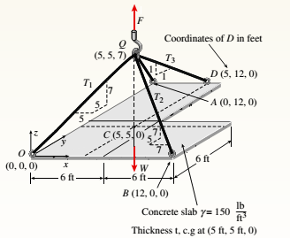
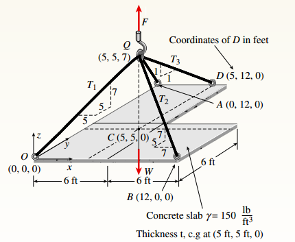
An L-shaped reinforced concrete slab 12 Ft X 12 ft, with a 6 Ft X 6 ft cut-out and thickness t = 9.0 in, is lifted by three cables attached at O, B, and D, as shown in the figure. The cables are are combined at point Q, which is 7.0 Ft above the top of the slab and directly above the center of mass at C. Each cable has an effective cross-sectional area of Ae= 0.12 in2.
(a) Find the tensile force Tr(i = 1, 2, 3) in each cable due to the weight W of the concrete slab
(ignore weight of cables).
(b) Find the average stress ov in each cable. (See Table I-1 in Appendix I for the weight density of reinforced concrete.)
(c) Add cable AQ so that OQA is one continuous cable, with each segment having Force T, which is connected to cables BQ and DQ at point Q. Repeat parts (a) and (b). Hini: There are now three Forced equilibrium equations and one constrain equation, T1= T4.
(a)
Tensile force T in each cable due to weight.
Answer to Problem 1.4.13P
Tensile force T is:
Explanation of Solution
Given Information:
You have the following figure with all relevant information:

Thickness (t) is 9 in.
Calculation:
Consider the free body diagram as:
To calculate external reaction force F, take equilibrium of forces as:
The following force acts on point Q:
Take equilibrium of forces at Q as:
Solve the above equation to get:
Conclusion:
Therefore, the correct answers are
(b)
Average stress in each cable.
Answer to Problem 1.4.13P
Stress in each cable is
Explanation of Solution
Given Information:
You have following figure with all relevant information:

Thickness (t) is 9 in. and cross-sectional area of each cable is
Calculation:
Consider the free body diagram as,

To calculate external reaction force F, take equilibrium of forces as,
The following forces acts on point Q:
Take equilibrium of forces at Q as:
Solve the above equation to get,
Calculate stress as,
Conclusion:
Therefore, the correct answer is:
(c)
Tensile force and average stress in each cable.
Answer to Problem 1.4.13P
Stress in each cable is:
Explanation of Solution
Given Information:
You have following figure with all relevant information:

Thickness (t) is 9 in. and cross-sectional area of each cable is
Calculation:
Consider the free body diagram as,

To calculate external reaction force F, take equilibrium of forces as:
The following force acts on point Q:
Take equilibrium of force at Q as:
Solve the above equation along with
Calculate stress as:
Conclusion:
Therefore, the correct answers are:
Want to see more full solutions like this?
Chapter 1 Solutions
Mechanics of Materials (MindTap Course List)


- (Read image)arrow_forward(Read Image)arrow_forwardM16x2 grade 8.8 bolts No. 25 C1- Q.2. The figure is a cross section of a grade 25 cast-iron pressure vessel. A total of N, M16x2.0 grade 8.8 bolts are to be used to resist a separating force of 160 kN. (a) Determine ks, km, and C. (b) Find the number of bolts required for a load factor of 2 where the bolts may be reused when the joint 19 mm is taken apart. (c) with the number of bolts obtained in (b), determine the realized load factor for overload, the yielding factor of safety, and the separation factor of safety. 19 mmarrow_forward
- Problem4. The thin uniform disk of mass m = 1-kg and radius R = 0.1m spins about the bent shaft OG with the angular speed w2 = 20 rad/s. At the same time, the shaft rotates about the z-axis with the angular speed 001 = 10 rad/s. The angle between the bent portion of the shaft and the z-axis is ẞ = 35°. The mass of the shaft is negligible compared to the mass of the disk. a. Find the angular momentum of the disk with respect to point G, based on the axis orientation as shown. Include an MVD in your solution. b. Find the angular momentum of the disk with respect to point O, based on the axis orientation as shown. (Note: O is NOT the center of fixed-point rotation.) c. Find the kinetic energy of the assembly. z R R 002 2R x Answer: H = -0.046ĵ-0.040 kg-m²/sec Ho=-0.146-0.015 kg-m²/sec T 0.518 N-m =arrow_forwardProblem 3. The assembly shown consists of a solid sphere of mass m and the uniform slender rod of the same mass, both of which are welded to the shaft. The assembly is rotating with angular velocity w at a particular moment. Find the angular momentum with respect to point O, in terms of the axes shown. Answer: Ñ。 = ½mc²wcosßsinßĵ + (}{mr²w + 2mb²w + ½ mc²wcos²ß) k 3 m r b 2 C لا marrow_forwardOnly question 2arrow_forward
- Only question 1arrow_forwardOnly question 3arrow_forwardI have Euler parameters that describe the orientation of N relative to Q, e = -0.7071*n3, e4 = 0.7071. I have Euler parameters that describe the orientation of U relative to N, e = -1/sqrt(3)*n1, e4 = sqrt(2/3). After using euler parameter rule of successive rotations, I get euler parameters that describe the orientation of U relative to Q, e = -0.4082*n1 - 0.4082*n2 - 0.5774*n3. I need euler parameters that describe the orientation of U relative to Q in vector basis of q instead of n. How do I get that?arrow_forward
- Describe at least 4 processes in engineering where control charts are (or should be) appliedarrow_forwardDescribe at least two (2) processes where control charts are (or should be) applied.arrow_forwardProblem 3: A cube-shaped spacecraft is in a circular Earth orbit. Let N (n,) be inertial and the spacecraft is denoted S (ŝ₁). The spacecraft is described such that ¯½º = J ŝ₁ŝ₁ + J ŝ₂§₂ + J §¸Ŝ3 Location of the spacecraft in the orbit is determined by the orbit-fixed unit vectors ê, that are oriented by the angle (Qt), where is a constant angular rate. 52 €3 3> 2t 55 Λ Из At the instant when Qt = 90°, the spacecraft S is oriented relative to the orbit such that 8₁ = 0° Space-three 1-2-3 angles 0₂ = 60° and ES = $₂ rad/s 0₁ = 135° (a) At this instant, determine the direction cosine matrix that describes the orientation of the spacecraft with respect to the inertial frame N.arrow_forward
 Mechanics of Materials (MindTap Course List)Mechanical EngineeringISBN:9781337093347Author:Barry J. Goodno, James M. GerePublisher:Cengage Learning