
Videos
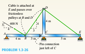
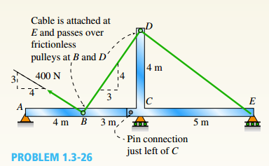
A plane frame with a pin support at A and roller supports at C and £ has a cable attached at E. which runs over Frictionless pulleys al D and B (see figure). The cable force is known to be 400 N. There is a pin connection just Lo the left of joint C.
(a) Find reactions at supports^, C, and E.
(b) Find internal stress, resultants N, V, and M just to the right of joint C.
(c) Find resultant force in the pin near C.
(a)
Reactions at supports A, C and E.
Answer to Problem 1.3.26P
The correct answers are:
Explanation of Solution
Given Information:
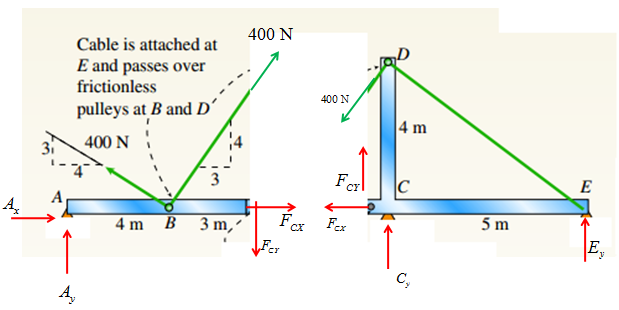
You have following figure with all relevant information:

Calculation:
Consider the following free body diagram:

Member AB :
Take equilibrium of moments about point B:
Take equilibrium of forces in
Take equilibrium of forces in
Member DCE :
Take equilibrium of moments about point C:
Take equilibrium of forces in
Take equilibrium of forces in
Now, solve equations (1-6) to get
Conclusion:
Thus, the reaction forces are:
(b)
Internal stress resultants N, V and M just to the right of C.
Answer to Problem 1.3.26P
The correct answers are:
Explanation of Solution
Given Information:
You have following figure with all relevant information:

Calculation of external forces:
Consider the following free body diagram:
Member AB :
Take equilibrium of moments about point B:
Take equilibrium of forces in
Take equilibrium of forces in
Member DCE :
Take equilibrium of moments about point C:
Take equilibrium of forces in
Take equilibrium of forces in
Now, solve equations (1-6) to get
Calculation of internal forces:
Consider the following free body diagram:
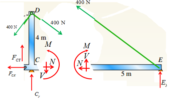
Consider the right hand side of the above free body diagram.
Take equilibrium of forces in
Take equilibrium of forces in
Take equilibrium of moments about point E:
Conclusion:
Thus, the internal forces are:
(c)
Resultant force in the pin near C.
Answer to Problem 1.3.26P
The correct answers are:
Explanation of Solution
Given Information:
You have following figure with all relevant information:
Calculation:
Consider the following free body diagram;

Member AB :
Take equilibrium of moments about point B:
Take equilibrium of forces in
Take equilibrium of forces in
Member DCE :
Take equilibrium of moments about point C,
Take equilibrium of forces in
Take equilibrium of forces in
Now, solve equations (1-6) to get:
Resultant force at pin near C is:
Conclusion:
Thus, the resultant force at pin near C is:
Want to see more full solutions like this?
Chapter 1 Solutions
Mechanics of Materials (MindTap Course List)


- 4. Figure 1 shows a pump and pipe network being used to transport heptane at 120°F to a large, elevated, closed storage tank. The tank is pressurized and maintained at 18 psia. The volumetric flow rate of the heptane is 500 gpm. a. Specify the nominal diameter of the check valve. b. Determine the pump discharge pressure required (psia) to move the heptane through the discharge pipe. Plank = 18 psia Liquid level Large pressurized storage tank 40 ft All pipes are 6-nom sch 40 commercial steel Standard 90° elbows and 180° bend Total length of straight pipe = 115 ft Class 300 swing check valve INH Pump Figure 1: Pressurized storage tank systemarrow_forward2. In a particular section of a fluid system, a 30% ethylene glycol mixture is flowing through a 6- nom xs cast iron pipe at a temperature of 0°C. In this section of piping, the velocity must be maintained in the range 1.5 m/sarrow_forward1. Steam leaves the boiler of a power plant at 5 MPa, 500°C as shown in the following figure. As the steam passes to the turbine, the temperature drops to 496°C before it enters the turbine due to a heat loss through the pipe's insulation. The pressure drop in the pipe connecting the boiler to the turbine is negligible. The steam then passes through an adiabatic turbine and exits at 10 kPa. The turbine has an isentropic efficiency of 85% and is delivering 1000 MW of power. Determine the following. P = 5 MPa T₁ = 500°C Boiler P₁₂ =5 MPa Τ =496°C 7 = 85% W = 1,000 MW P=1 atm To=25°C Turbine 3+ P = 10 kPa a. The heat transfer rate from the pipe connecting the boiler to the turbine (in MW) b. The change in flow exergy rate as the steam flows through the pipe (MW). This represents exergy that is lost to the environment and unavailable for power delivery. Comment on the magnitude of this exergy loss compared to the power delivered by the turbine. What factor(s) would warrant better…arrow_forwardAn aluminum rod of length L = 1m has mass density p = 2700 kg and Young's modulus E = 70 GPa. The rod is fixed at both ends. The exact natural eigenfrequencies of the rod are wexact E = √ ρ for n=1,2,3,. . . . 1. What is the minimum number of linear elements necessary to determine the fundamental frequency w₁ of the system? Discretize the rod in that many elements of equal length, assemble the global system of equations KU = w² MU, and find the fundamental frequency w₁. Compute the relative error e₁ = (w1 - wexact) /w exact Sketch the fundamental mode of vibration. 2. Use COMSOL to solve the same problem. Show the steps necessary to find the fundamental frequency and mode of the rod. What is the relative error using linear elements and a normal mesh?arrow_forwardA ball with a mass of 5.0 kg is hanging from a string and is initially at rest. A bullet with a mass of 10.0 g and a velocity of 200.0 m/s is fired at the ball. The bullet embeds itself inside the ball. How high (h) do the ball and the bullet rise? Gravitational acceleration: g=9.81g = 9.81g=9.81 m/s².arrow_forwardDon't use chatgpt. Need handwritten solution. Mechanical engineeringarrow_forwardMechanical engineering question.arrow_forwardA shaft is loaded in bending and torsion such that Ma = 70 N·m, T₁ = 45 N · m, M = 55 N. m, and T = 35 N m. For the shaft, S₁ = 700 MPa and S = 560 MPa, and a fully corrected endurance limit of S₂ = 210 MPa is assumed. Let K = 2.2 and K = 1.8. With a Se design factor of 2.0 determine the minimum acceptable diameter of the shaft using the a) DE- Goodman b) DE-Morrow c) DE-Gerber d) DE-SWTarrow_forwardThe feed flow rate to an adiabatic continuous stirred tank reactor (CSTR) in which an exothermicreaction is occurring is increased from 1000 to 1400. kg/h, causing the outlet temperature to change as shown:a) Briefly explain on a physical basis why the temperature in this system oscillates after a step increasein the inlet flow rate. Be clear, complete, and concise. c) You know that this oscillating response cannot be that of two first order processes with real timeconstant acting in series. Assuming the reaction is first order and the CSTR operates with constant holdup,derive the block diagram with all transfer functions indicating how the temperature would respond to the feedflow rate step change (W’(s) as input and T’(s) as output). An intermediate variable in this block diagram willbe the concentration of A in the reactor, represented by CA’(s). d) A correct result for part c) will include a feedback loop in the block diagram, indicating the responsein T to a change in w is not…arrow_forwardSpur gears Note : Exam is open notes &tables / Answer all questions. Q.1. The press shown for Figure.1 has a rated load of 22 kN. The twin screws have double start Acme threads, a diameter of 50 mm, and a pitch of 6 mm. Coefficients of friction are 0.05 for the threads and 0.08 for the collar bearings. Collar diameters are 90 mm. The gears have an efficiency of 95 percent and a speed ratio of 60:1. A slip clutch, on the motor shaft, prevents overloading. The full-load motor speed is 1720 rev/min. (a) When the motor is turned on, how fast will the press head move? (Vm= , Vser. = ) (5M) (b) What should be the horsepower rating of the motor? (TR=, Tc= Pser. = " Bronze bushings Foot Motor Bearings watt, Pm= watt, Pm= h.p.) (20M) 2['s Fig.1 Worm Collar bearingarrow_forwardProblem 2 (55 pts). We now consider the FEM solution of Problem 1.(a) [5pts] Briefly describe the 4 steps necessary to obtain the approximate solution of thatBVP using the Galerkin FEM. Use the minimum amount of math necessary to supportyour explanations.(b) [20pts] Derive the weak form of the BVP.(c) [10pts] Assuming a mesh of two equal elements and linear shape functions, sketch byhand how you expect the FEM solution to look like. Also sketch the analytical solutionfor comparison. In your sketch, identify the nodal degrees of freedom that the FEMsolution seeks to find.(d) [10pts] By analogy with the elastic rod problem and heat conduction problem considered in class, write down the stiffness matrix and force vector for each of the twoelements considered in (c).(e) [10pts] Assemble the global system of equations, and verbally explain how to solve it.arrow_forwardAn aluminum rod of length L = 1m has mass density ρ = 2700 kgm3 andYoung’s modulus E = 70GPa. The rod is fixed at both ends. The exactnatural eigenfrequencies of the rod are ωexactn =πnLqEρfor n=1,2,3,. . . .1. What is the minimum number of linear elements necessary todetermine the fundamental frequency ω1 of the system? Discretizethe rod in that many elements of equal length, assemble the globalsystem of equations KU = ω2MU, and find the fundamentalfrequency ω1. Compute the relative error e1 = (ω1 − ωexact1)/ωexact1.Sketch the fundamental mode of vibration.arrow_forwardarrow_back_iosSEE MORE QUESTIONSarrow_forward_ios
 Mechanics of Materials (MindTap Course List)Mechanical EngineeringISBN:9781337093347Author:Barry J. Goodno, James M. GerePublisher:Cengage Learning