
Concept explainers
Videos
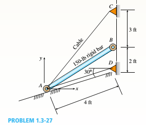
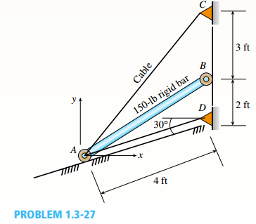
A 150-lb rigid bar AB. with friction less rollers al each end. is held in the position shown in the figure by a continuous cable CAD. The cable is pinned at C and D and runs over a pulley at A.
(a) Find reactions at supports A and B.
(b) Find the force in the cable.
(a)
Reactions at supports A, and B.
Answer to Problem 1.3.27P
The correct answers are:
Explanation of Solution
Given Information:
You have a 150 lb rigid bar AB, with frictionless rollers at each end held with cables as shown in the figure below:
Calculation:
Consider the following diagram,

Calculate the position of D as,
Calculate the position of B as,
Calculate the position of C as,
Calculate the position of center of gravity as,
Calculate angle
Calculate the angle
Consider the following free body diagram,
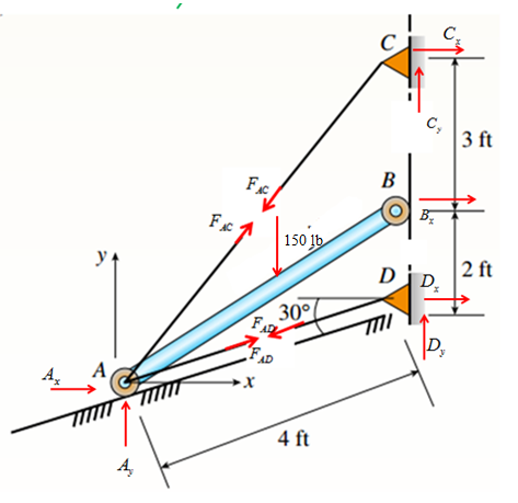
Member AB :
Take equilibrium of moments about point A,
Take equilibrium of forces in
Take equilibrium of forces in
Analyze Joint C :
Consider free body diagram at C.
Take equilibrium of forces in
Take equilibrium of forces in
Analyze Joint D :
Consider free body diagram at D.
Take equilibrium of forces in
Take equilibrium of forces in
Also since the same cable rolls, hence
Also take equilibrium of the forces along AD for member AB as,
Now, solve equations (1-9) to get
Conclusion:
Thus the reaction forces are:
(b)
Reaction force in cable.
Answer to Problem 1.3.27P
The tension force in cable is 71.6 lb.
Explanation of Solution
Given Information:
You have a 150 lb rigid bar AB, with frictionless rollers at each end held with cables as shown in figure below,

Calculation:
Consider the following diagram,

Calculate position of D as,
Calculate position of B as,
Calculate position of C as,
Calculate position of center of gravity as,
Calculate angle
Calculate angle
Consider the following free body diagram,

Member AB :
Take equilibrium of moments about point A,
Take equilibrium of forces in
Take equilibrium of forces in
Analyze Joint C :
Consider free body diagram at C.
Take equilibrium of forces in
Take equilibrium of forces in
Analyze Joint D :
Consider free body diagram at D.
Take equilibrium of forces in
Take equilibrium of forces in
Also since the same cable rolls, hence
Also take equilibrium of the forces along AD for member AB as,
Now, solve equations (1-9) to get
Conclusion:
The tension force in cable is 71.6 lb.
Want to see more full solutions like this?
Chapter 1 Solutions
Mechanics of Materials (MindTap Course List)


- A piston–cylinder device contains 50 kg of water at 250 kPa and 25°C. The cross-sectional area of the piston is 0.1 m2. Heat is now transferred to the water, causing part of it to evaporate and expand. When the volume reaches 0.26 m3, the piston reaches a linear spring whose spring constant is 100 kN/m. More heat is transferred to the water until the piston rises 20 cm more. NOTE: This is a multi-part question. Once an answer is submitted, you will be unable to return to this part. Determine the final pressure and temperature. The final pressure is kPa. The final temperature is ºC. Find the work done during the processarrow_forwardA garden hose attached with a nozzle is used to fill a 20-gal bucket. The inner diameter of the hose is 1 in and it reduces to 0.53 in at the nozzle exit. The average velocity in the hose is 8 ft/s and the density of water is 62.4 lbm/ft3. NOTE: This is a multi-part question. Once an answer is submitted, you will be unable to return to this part. Determine the volume and mass flow rates of water through the hose. The volume flow rate of water through the hose is ft3/s. The mass flow rate of water through the hose is lbm/s. The change in time? What is the exit velocity?arrow_forwardA 23-ft3 rigid tank initially contains saturated refrigerant-134a vapor at 160 psia. As a result of heat transfer from the refrigerant, the pressure drops to 50 psia. NOTE: This is a multi-part question. Once an answer is submitted, you will be unable to return to this part. Determine the final temperature. Use data from refrigerant tables. The final temperature is ºF.arrow_forward
- A 23-ft3 rigid tank initially contains saturated refrigerant-134a vapor at 160 psia. As a result of heat transfer from the refrigerant, the pressure drops to 50 psia. NOTE: This is a multi-part question. Once an answer is submitted, you will be unable to return to this part. Determine the heat transfer. The heat transfer is Btu.arrow_forwardThe shaft shown in the figure below is subjected to axial loads as illustrated. The diameters of segments AB, BC, and CD are 20mm, 25mm, and 15mm, respectively. If the modulus of elasticity of the material is 610 MPa. Determine the change of A to D lengtharrow_forwardDetermine the final pressure and temperature. The final pressure is kPa. The final temperature is ºC.arrow_forward
- Air enters the 1-m2 inlet of an aircraft engine at 100 kPa and 20°C with a velocity of 184 m/s. Determine the volume flow rate, in m3/s, at the engine’s inlet and the mass flow rate, in kg/s, at the engine’s exit. The gas constant of air is R = 0.287 kPa·m3/kg·K. The volume flow rate at the engine’s inlet m3/s. The mass flow rate at the engine’s exit is kg/s.arrow_forwardThe ventilating fan of the bathroom of a building has a volume flow rate of 33 L/s and runs continuously. If the density of air inside is 1.20 kg/m3, determine the mass of air vented out in one day. The mass of air is kg.arrow_forwardA steady-flow compressor is used to compress helium from 15 psia and 70°F at the inlet to 200 psia and 600°F at the outlet. The outlet area and velocity are 0.01 ft2 and 100 ft/s, respectively, and the inlet velocity is 53 ft/s. Determine the mass flow rate and the inlet area. The gas constant of helium is R = 2.6809 psia·ft3/lbm·R. The mass flow rate is lbm/s. The inlet area is ft2.arrow_forward
- 1. The maximum and minimum stresses as well as the shear stress seen subjected the piece in plane A-A. Assume it is a cylinder with a diameter of 12.7mm 2. Draw the Mohr circle for the stress state using software. 3. Selection of the material for the prosthesis, which must be analyzed from the point of safety and cost view.arrow_forwardMarrow_forward× Your answer is incorrect. (Manometer) Determine the angle 0 of the inclined tube shown in figure below if the pressure at A is 1 psi greater than that at B. 1ft SG=0.61 十 A Ꮎ 1ft SG=1.0 8.8 ft 0 = Hi 15.20 deg Airarrow_forward
 Mechanics of Materials (MindTap Course List)Mechanical EngineeringISBN:9781337093347Author:Barry J. Goodno, James M. GerePublisher:Cengage Learning