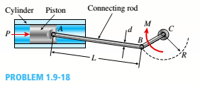
Problem 1.3.1P: Find support reactions at A and B and then calculate the axial force N. shear force J and bending... Problem 1.3.2P: Find support reactions at A and B and then calculate the axial force N, shear force V, and bending... Problem 1.3.3P: Segments AB and BC of beam ABC are pin connected a small distance to the right of joint B (sec... Problem 1.3.4P: Segments A B and BCD of beam A BCD are pin connected at x = 4 m. The beam is supported by a sliding... Problem 1.3.5P: Segments AB and BCD of beam ABCD are pin connected at x = 10 ft. The beam is supported by a pin... Problem 1.3.6P: Consider the plane truss with a pin support at joint 3 and a crtica1 roller support at joint 5 (see... Problem 1.3.7P: A plane truss has a pin support at A and a roller support at E(see figure). (a) Find reactions at... Problem 1.3.8P: A plane truss has a pin support at F and a roller support at D (see figure). (a) Find reactions at... Problem 1.3.9P: Find support reactions at A and B and then use the method of joints to find all member forces. Let c... Problem 1.3.10P: Find support reactions at 4 and Band then use the method of joints to find all member forces. Let b... Problem 1.3.11P: Repeat 1.3-9 but use the method of sections go find member forces in AC and BD. Problem 1.3.12P: Repeat 1.3-10 but use the method of sections to find member forces in AB and DC. Problem 1.3.13P: A space truss has three-dimensional pin supports at joints 0, B, and C, Load P is applied at joint A... Problem 1.3.14P: A space truss is restrained at joints O, A. B. and C, as shown in the figure. Load P is applied at... Problem 1.3.15P: 1.3-15 A space truss is restrained at joints A, B, and C, as shown in the figure. Load 2P is applied... Problem 1.3.16P: A space truss is restrained at joints A, B. and C, as shown in the figure. Load P acts in the +z... Problem 1.3.17P: A stepped shaft ABC consisting of two solid, circular segments is subjected to torques T}and... Problem 1.3.18P: A stepped shaft ABC consisting of two solid, circular segments is subjected to uniformly distributed... Problem 1.3.19P: A plane frame is restrained al joints A and C, as shown in the figure. Members AB and BC are pin... Problem 1.3.20P: A plane Frame is restrained at joints A and D, as shown in the figure. Members AB and BCD are pin... Problem 1.3.21P: Find support reactions at A and D and then calculate the axial force N, shear force V, and bending... Problem 1.3.22P: Find support reactions at A and D and then calculate the axial force N. shear force 1 and bending... Problem 1.3.23P: ,3-23 A 200-lb trap door (AD) is supported by a strut (BC) which is pin connected to the door at B... Problem 1.3.24P: A plane frame is constructed by using a pin connection between segments ABC and CDE. The frame has... Problem 1.3.25P: A plane Frame with pin supports at A and E has a cable attached at C, which runs over a... Problem 1.3.26P: A plane frame with a pin support at A and roller supports at C and £ has a cable attached at E.... Problem 1.3.27P: A 150-lb rigid bar AB. with friction less rollers al each end. is held in the position shown in the... Problem 1.3.28P: A plane frame has a pin support at A and roller supports at C and E (see figure). Frame segments A... Problem 1.3.29P: A special vehicle brake is clamped at O when the brake force P1 is applied (see figure). Force P1=... Problem 1.3.30P: Space frame A BCD is clamped at A, except it is Free to translate in the .v direction. There is also... Problem 1.3.31P: Space Frame ABC is clamped at A, except it is free to rotate at A about the x and y axes. Cables DC... Problem 1.3.32P: A soccer goal is subjected to gravity loads (in the - z direction, w = 73 N/m for DG, BG, and BC; w... Problem 1.3.33P: An elliptical exerciser machine (see figure part a) is composed of front and back rails. A... Problem 1.3.34P: A mountain bike is moving along a flat path at constant velocity. At some instant, the rider (weight... Problem 1.4.1P: A hollow circular post ABC (see figure) supports a load Pt= 1700 lb acting al the top. A second load... Problem 1.4.2P: A circular nylon pipe supports a downward load PA= 10 kN. which is uniformly distributed around a... Problem 1.4.3P: A circular tube AB is fixed at one end and free at the other end. The tube is subjected to axial... Problem 1.4.4P: A force P of 70 N is applied by a rider to the front hand brake of a bicycle ( P is the resultant of... Problem 1.4.5P: A bicycle rider wants to compare the effectiveness of cantilever hand brakes (see figure part a)... Problem 1.4.6P: A circular aluminum tube with a length of L = 420 mm is loaded in compression by forces P (see... Problem 1.4.7P: The cross section of a concrete corner column that is loaded uniformly in compression is shown in... Problem 1.4.8P: A car weighing 130 kN when fully loaded is pulled slowly up a steep inclined track by a steel cable... Problem 1.4.9P: Two steel wines support a moveable overhead camera weighing W = 28 lb (see figure part a) used For... Problem 1.4.10P: A long re Lai nine: wall is braced by wood shores set at an angle of 30° and supported by concrete... Problem 1.4.11P: A pickup truck tailgate supports a crate where Wc= 150 lb. as shown in the figure. The tailgate... Problem 1.4.12P: Solve the preceding problem if the mass of the tailgate is MT— 11 kg and that of the crate is hic—... Problem 1.4.13P: An L-shaped reinforced concrete slab 12 Ft X 12 ft, with a 6 Ft X 6 ft cut-out and thickness t = 9.0... Problem 1.4.14P: A crane boom of mass 450 leg with its center of mass at C is stabilized by two cables AQ and BQ (Ae=... Problem 1.4.15P: Two gondolas on a ski lift are locked in the position show in the figure while repairs are being... Problem 1.4.16P: A round bar ABC of length 2L (see figure) rotates about an axis through the midpoint C with constant... Problem 1.4.17P: Two separate cables AC and BC support a sign structure of weight W = 1575 lb attached to a building.... Problem 1.5.1P: Imagine that a long steel wire hangs vertically from a high-altitude balloon. (a) What is the... Problem 1.5.2P: A steel riser pipe hangs from a drill rig located offshore in deep water (see figure). (a) What is... Problem 1.5.3P: Three different materials, designated A, B. and C, are tested in tension using test specimens having... Problem 1.5.4P: The strength-to-weight ratio of a structural material is defined as its load-carrying capacity... Problem 1.5.5P: A symmetrical framework consisting of three pin-connected bars is loaded by a force P (see figure).... Problem 1.5.6P: A specimen of a methacrylate plastic is tested in tension at room temperature (see figure},... Problem 1.5.7P: The data shown in the accompanying table are From a tensile test of high-strength steel. The test... Problem 1.6.1P: A bar made of structural steel having the stress-strain diagram shown in the figure has a length of... Problem 1.6.2P: A bar of length 2.0 m is made of a structural steel having the stress-strain diagram shown in the... Problem 1.6.3P: A bar made of structural steel having the stress-strain diagram shown in the figure has a length of... Problem 1.6.4P: A circular bar of magnesium alloy is 750 mm long. The stress-strain diagram for the material is... Problem 1.6.5P: An aluminum bar has length L = 6 ft and diameter d = 1.375 in. The stress-strain curse for the... Problem 1.6.6P: A continuous cable (diameter 6 mm) with tension force T is attached to a horizontal frame member at... Problem 1.6.7P: A wine of length L = 4 ft and diameter d = 0.125 in. is stretched by tensile forces P = 600 lb. The... Problem 1.7.1P: A high-strength steel bar used in a large crane has a diameter d = 2.00 in. (sec figure). The steel... Problem 1.7.2P: A round bar of 10 mm diameter is made of aluminum alloy 7075-T6 (see figure). When the bar is... Problem 1.7.3P: A polyethylene bar with a diameter d, = 4.0 in. is placed inside a steel lube with an inner diameter... Problem 1.7.4P: A square plastic bar (length LP,side dimension sP=193 mm) is inserted inside a hollow. square cast... Problem 1.7.5P: A polyethylene bar having rectangular cross section with a width 7.35 in. and depth 7 in. is placed... Problem 1.7.6P: A circular aluminum tube of length L = 600 mm is loaded in compression by forces P (see figure). The... Problem 1.7.7P: A bar of monel metal with a length L = 9 in. and a diameter d = 0225 in. is loaded axially by a... Problem 1.7.8P: A tensile test is performed on a brass specimen 10 mm in diameter using a gage length of 50 mm (see... Problem 1.7.9P: A hollow, brass circular pipe ABC (see figure) supports a load P1= 26.5 kips acting at the top. A... Problem 1.7.10P: Three round, copper alloy bars having the same length L but different shapes are shown, in the... Problem 1.8.1P: An angle bracket having a thickness t = 0.75 in. is attached to the flange of a column by two... Problem 1.8.2P: Truss members supporting a roof are connected to a 26-mm-thick gusset plate by a 22-mm diameter pin,... Problem 1.8.3P: The upper deck ala foothill stadium is supported by braces, each of which transfer a load P = 160... Problem 1.8.4P: The inclined ladder AB supports a house painter (85 kg) at C and the weight iq = 40 K/m} of the... Problem 1.8.5P: The Force in the brake cable of the V-brake system shown in the figure is T — 45 lb. The pivot pin... Problem 1.8.6P: A steel plate of dimensions 2.5 × l.5 × 0.08 m and weighing 23.1 kN is hoisted by steel cables with... Problem 1.8.7P: A special-purpose eye boll with a shank diameter d - 0.50 in. passes through, a hole in a steel... Problem 1.8.8P: An elastomeric bearing pad consisting of two steel plates bonded to a chloroprene elastomer (an... Problem 1.8.9P: A joint between iwo concrete slabs A and B is filled, with a flexible epoxy lhal bonds securely lo... Problem 1.8.10P: A steel punch consists of two shafts: upper shaft and lower shaft. Assume that the upper shaft has a... Problem 1.8.11P: A joint between two glass plates A and B is filled with a flexible epoxy that bonds securely to the... Problem 1.8.12P: A punch for making a slotted hole in ID cards is shown in the figure part a. Assume that the hole... Problem 1.8.13P: A steel riser pipe hangs from a drill rig located offshore in deep water (see figure). Separate... Problem 1.8.14P: A flexible connection consisting of rubber pads (thickness f = 9 mm) bonded to steel plates is shown... Problem 1.8.15P: .15 A hitch-mounted bicycle rack is designed to carry up to four 30-lb bikes mounted on and strapped... Problem 1.8.16P: The clamp shown in the figure supports a load hanging from the lower flange of a steel beam. The... Problem 1.8.17P: A shock mount constructed as shown iu the figure is used to support a delicate instrument. The mount... Problem 1.8.18P Problem 1.8.19P: A spray nozzle for a garden hose requires under a water pressure force fp= 30 lb at C (see figure a... Problem 1.8.20P: A single steel strut AB with a diameter (a) Find the strut force Fs and average normal stress ds= 8... Problem 1.8.21P: The top portion of a pole saw used to trim (a) Find the force P on the cutting Made at D if tbe... Problem 1.8.22P: A cargo ship is tied down to marine boll arts at a number of points along its length while its cargo... Problem 1.8.23P: A basketball player hangs on the rim after (a) Find the reactions at the support bracket a dunk. He... Problem 1.8.24P: A bicycle chain consists of a series of small links, where each are 12 mm long between the centers... Problem 1.9.1P: A bar of solid circular cross section is loaded in tension by forces P (see figure). The bar has a... Problem 1.9.2P: .2 A torque T0is transmitted between two flanged shafts by means of ten 20-mm bolts (see figure and... Problem 1.9.3P: A tie-down on the deck of a sailboat consists of a bent bar boiled at both ends, as shown in the... Problem 1.9.4P: Two steel tubes are joined at B by four pins (dp= 11 mm), as shown in the cross section a—a in the... Problem 1.9.5P: A steel pad supporting heavy machinery rests on Four short, hollow, cast iron piers (see figure).... Problem 1.9.6P: A steel pad supporting heavy machinery rests on four short, hollow, cast iron piers (see figure).... Problem 1.9.7P: A steel riser pipe hangs from a drill rig. Individual segments of equal length L = 50 ft are joined... Problem 1.9.8P: The rear hatch of a van (BDCG in figure part a) is supported by two hinges at Bland B2and by two... Problem 1.9.9P: A lifeboat hangs from two ship's davits. as shown in the figure. A pin of diameter d = 0.80 in.... Problem 1.9.10P: A cable and pulley system in the figure part a supports a cage of a mass 300 kg at B. Assume that... Problem 1.9.11P: A ship's spar is attached at the base of a mast by a pin connection (see figure). The spar is a... Problem 1.9.12P: What is the maximum possible value of the clamping Force C in the jaws of the pliers shown in the... Problem 1.9.13P: A metal bar AB of a weight Ills suspended by a system of steel wires arranged as shown in the... Problem 1.9.14P: A plane truss is subjected to loads 2P and P at joints B and C, respectively, as shown in the figure... Problem 1.9.15P: A solid bar of circular cross section (diameter d) has a hole of diameter d/5 drilled laterally... Problem 1.9.16P: A solid steel bar of a diameter d1= 60 mm has a hole of a diameter d2= 32 mm drilled through it (see... Problem 1.9.17P: A sign of weight W is supported at its base by four bolls anchored in a concrete footing. Wind... Problem 1.9.18P: The piston in an engine is attached to a connecting rod AB, which in turn is connected to a crank... Problem 1.10.1P: An aluminum tube is required to transmit an axial tensile force P = 33 k (sec figure part a). The... Problem 1.10.2P: A copper alloy pipe with a yield stress aY= 290 MPa. is to carry an axial tensile load P = 1500 kN... Problem 1.10.3P: A horizontal beam AB with cross-sectional dimensions (b = 0.75 in.) X (h = 8.0 in.) is supported by... Problem 1.10.4P: Lateral bracing for an elevated pedestrian walkway is shown in the figure part a. The thickness of... Problem 1.10.5P: A plane truss has joint loads P, 2P, and 3P at joints D. C, and B. respectively (see figure) where... Problem 1.10.6P: Cable DB supports canopy beam OABC as shown in the figure. Find the required cross-sectional area of... Problem 1.10.7P: Continuous cable ADS runs over a small Frictionless pulley at D to support beam OABC that is part of... Problem 1.10.8P: A suspender on a suspension bridge consist of a cable that passes over the main cable (see figure)... Problem 1.10.9P: A square steel tube of a length L = 20 ft and width b2= 10.0 in. is hoisted by a crane (see figure).... Problem 1.10.10P: A cable and pulley system at D is used to bring a 230-lcg pole (ACB) to a vertical position, as... Problem 1.10.11P: A pressurized circular cylinder has a sealed cover plate fastened with steel bolts (see figure). The... Problem 1.10.12P: A tubular post of outer diameter d2is guyed by two cables fitted with turnbuckles (see figure). The... Problem 1.10.13P: A large precast concrete panel for a warehouse is raised using two sets of cables at two lift lines,... Problem 1.10.14P: A steel column of hollow circular cross section is supported on a circular, steel base plate and a... Problem 1.10.15P: An elevated jogging track is supported at intervals by a wood beam AB (L = 7.5 ft) that is pinned at... Problem 1.10.16P: A flat bar of a widths b = 60 mm and thickness t = 10 mm is loaded in tension by a force p (see... Problem 1.10.17P: Continuous cable A DB runs over a small friction less pulley al D to support beam OABC, which is... Problem 1.10.18P: Continuous cable ADB runs over a small friction less pulley at D to support beam OABC, which is pan... Problem 1.10.19P: Two bars AC and BC of the same material support a vertical load P (see figure). The length L of the... format_list_bulleted


 Mechanics of Materials (MindTap Course List)Mechanical EngineeringISBN:9781337093347Author:Barry J. Goodno, James M. GerePublisher:Cengage Learning