Concept explainers
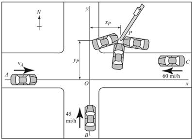
Knowing that the coordinates of the utility pole are
(a)
Time elapsed from first collision to the stop at
Answer to Problem 14.20P
The time elapsed from first collision to stop at pole is
Explanation of Solution
Given:
Speed of car B is
Speed of car C is
Weight if car A is
Weight of car B is
Weight of car C is
Coordinates of utility pole are
Concept used:
Draw the diagram for the system mentioned as shown below:

Assume origin as point O where, Car A and Car B collides.
Write the expression for the mass center of first collision.
Multiply the whole equation (1) with
Here,
Write the expression for conservation of momentum for the system.
Multiply the equation (3) with
Here,
Write the expression for the position of pole
Here,
Calculation:
Substitute
Equate
Equate
Substitute
Substitute
Substitute
Equate
Rearrange the above expression for
The time elapsed from first collision to stop at pole is
Conclusion:
Thus, the time elapsed from first collision to stop at pole is
(b)
Speed of car A.
Answer to Problem 14.20P
The velocity of car A is
Explanation of Solution
Calculation:
Substitute
Substitute
Equate the
Substitute
Simplify above expression for
The velocity of car A is
Conclusion:
Thus, the velocity of car A is
Want to see more full solutions like this?
Chapter 14 Solutions
Vector Mechanics for Engineers: Dynamics
- - | العنوان In non-continuous dieless drawing process for copper tube as shown in Fig. (1), take the following data: Do-20mm, to=3mm, D=12mm, ti/to=0.6 and v.-15mm/s. Calculate: (1) area reduction RA, (2) drawing velocity v. Knowing that: ti: final thickness V. Fig. (1) ofthrearrow_forwardA direct extrusion operation produces the cross section shown in Fig. (2) from an aluminum billet whose diameter 160 mm and length - 700 mm. Determine the length of the extruded section at the end of the operation if the die angle -14° 60 X Fig. (2) Note: all dimensions in mm.arrow_forwardFor hot rolling processes, show that the average strain rate can be given as: = (1+5)√RdIn(+1)arrow_forward
- : +0 usão العنوان on to A vertical true centrifugal casting process is used to produce bushings that are 250 mm long and 200 mm in outside diameter. If the rotational speed during solidification is 500 rev/min, determine the inside radii at the top and bottom of the bushing if R-2R. Take: -9.81 mis ۲/۱ ostrararrow_forward: +0 العنوان use only In conventional drawing of a stainless steel wire, the original diameter D.-3mm, the area reduction at each die stand r-40%, and the proposed final diameter D.-0.5mm, how many die stands are required to complete this process. онarrow_forwardIn non-continuous dieless drawing process for copper tube as shown in Fig. (1), take the following data: Do-20mm, to=3mm, D=12mm, ti/to=0.6 and vo-15mm/s. Calculate: (1) area reduction RA, (2) drawing velocity v. Knowing that: t₁: final thickness D₁ V. Fig. (1) Darrow_forward
- A vertical true centrifugal casting process is used to produce bushings that are 250 mm long and 200 mm in outside diameter. If the rotational speed during solidification is 500 rev/min, determine the inside radii at the top and bottom of the bushing if R-2Rb. Take: 8-9.81 m/sarrow_forwardIn conventional drawing of a stainless steel wire, the original diameter D.-3mm, the area reduction at each die stand r-40%, and the proposed final diameter D₁-0.5mm, how many die stands are required to complete this process.arrow_forwardA vertical true centrifugal casting process is used to produce bushings that are 250 mm long and 200 mm in outside diameter. If the rotational speed during solidification is 500 rev/min, determine the inside radii at the top and bottom of the bushing if R-2Rb. Take: 8-9.81 m/sarrow_forward
- In non-continuous dieless drawing process for copper tube as shown in Fig. (1), take the following data: Do-20mm, to=3mm, D=12mm, ti/to=0.6 and vo-15mm/s. Calculate: (1) area reduction RA, (2) drawing velocity v. Knowing that: t₁: final thickness D₁ V. Fig. (1) Darrow_forward-6- 8 من 8 Mechanical vibration HW-prob-1 lecture 8 By: Lecturer Mohammed O. attea The 8-lb body is released from rest a distance xo to the right of the equilibrium position. Determine the displacement x as a function of time t, where t = 0 is the time of release. c=2.5 lb-sec/ft wwwww k-3 lb/in. 8 lb Prob. -2 Find the value of (c) if the system is critically damping. Prob-3 Find Meq and Ceq at point B, Drive eq. of motion for the system below. Ш H -7~ + 目 T T & T тт +arrow_forwardQ For the following plan of building foundation, Determine immediate settlement at points (A) and (B) knowing that: E,-25MPa, u=0.3, Depth of foundation (D) =1m, Depth of layer below base level of foundation (H)=10m. 3m 2m 100kPa A 2m 150kPa 5m 200kPa Barrow_forward
 Elements Of ElectromagneticsMechanical EngineeringISBN:9780190698614Author:Sadiku, Matthew N. O.Publisher:Oxford University Press
 Mechanics of Materials (10th Edition)Mechanical EngineeringISBN:9780134319650Author:Russell C. HibbelerPublisher:PEARSON
 Thermodynamics: An Engineering ApproachMechanical EngineeringISBN:9781259822674Author:Yunus A. Cengel Dr., Michael A. BolesPublisher:McGraw-Hill Education
 Control Systems EngineeringMechanical EngineeringISBN:9781118170519Author:Norman S. NisePublisher:WILEY
 Mechanics of Materials (MindTap Course List)Mechanical EngineeringISBN:9781337093347Author:Barry J. Goodno, James M. GerePublisher:Cengage Learning
 Engineering Mechanics: StaticsMechanical EngineeringISBN:9781118807330Author:James L. Meriam, L. G. Kraige, J. N. BoltonPublisher:WILEY


