Videos
(a)
The mass flow rate of the refrigerant through the upper compression cycle.
(a)
Answer to Problem 59P
The mass flow rate of the refrigerant through the upper compression cycle is
Explanation of Solution
Sketch the schematic diagram for the two stage cascade refrigeration system as in Figure (1).
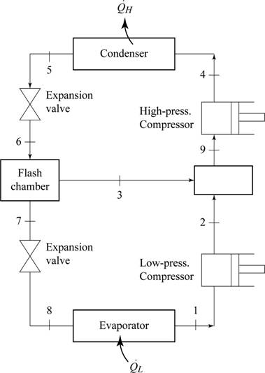
Write the relation between the specific enthalpies at the inlet and exit of throttling process.
Here, specific enthalpy at the inlet of throttling is
Write the expression for the isentropic efficiency of the compressor
Here, specific enthalpy at the isentropic exit of compressor is
Write the formula to calculate the dryness fraction at the exit of expansion valve
Here, specific enthalpy of refrigerant at expansion valve exit is
Write the expression for the mass flow rate of refrigerant
Here, mass flow rate of refrigerant at the inlet of low pressure compressor is
Conclusion:
From the Table A-12 of “Saturated refrigerant R-134a: Pressure”, obtain the properties of refrigerant at low pressure compressor inlet pressure
Here, specific enthalpy of the saturated vapor is
The specific entropy at the end of isentropic compression
Refer to Table A-13, “Superheated R-134a”, and obtain the values of R-134a at pressure of
Substitute
From the Table A-12 of “Saturated refrigerant R-134a: Pressure”, obtain the properties of refrigerant at throttling inlet pressure
From the Table A-12 of “Saturated refrigerant R-134a: Pressure”, obtain the properties of refrigerant at second stage compressor inlet pressure
Substitute
From the Table A-12 of “Saturated refrigerant R-134a: Pressure”, obtain the properties of refrigerant at second stage expansion inlet pressure
Substitute
From the Table A-12 of “Saturated refrigerant R-134a: Pressure”, obtain the properties of refrigerant at pressure
Substitute
Substitute
The mass flow rate of the refrigerant through the upper compression cycle is
(b)
The rate at which heat removed from the refrigerated space.
(b)
Answer to Problem 59P
The rate at which heat removed from the refrigerated space is
Explanation of Solution
Write the mass balance equation for the
Write the energy balance equation for the flash chamber.
Here, specific enthalpy at state 9 is
Write the formula to calculate the rate of heat transfer from the refrigerated space
Conclusion:
Refer to Table A-13, “Superheated R-134a”, and obtain the values of R-134a at pressure of
The specific entropy at the end of isentropic compression
Refer to Table A-13, “Superheated R-134a”, and obtain the values of R-134a at pressure of
Substitute
Substitute
Thus, the rate at which heat removed from the refrigerated space is
(c)
The power input required to the two stage cascade refrigeration system.
The coefficient of refrigeration for the two-stage cascade refrigeration system.
(c)
Answer to Problem 59P
The power input required to the two stage cascade refrigeration system is
The coefficient of refrigeration for the two-stage cascade refrigeration system is
Explanation of Solution
Write the formula to calculate the total required work input
Here, required work input to the first stage compression is
Write the formula to calculate the COP of the two-stage cascade refrigeration system.
Conclusion:
Substitute
Thus, the power input required to two stage cascade refrigeration system is
Substitute 26.35 kW for
Thus, the coefficient of refrigeration for the two-stage cascade refrigeration system is
(d)
The rate at which heat removed from the refrigerated space.
The coefficient of refrigeration for the two-stage cascade refrigeration system.
(d)
Answer to Problem 59P
The rate at which heat removed from the refrigerated space is
The coefficient of refrigeration for the two-stage cascade refrigeration system is
Explanation of Solution
Write the formula to calculate the rate of heat transfer from the refrigerated space
Here, the specific enthalpy of refrigerant at the exit of expansion valve is
Write the formula to calculate the required work input
Conclusion:
From the Table A-12 of “Saturated refrigerant R-134a: Pressure”, obtain the properties of refrigerant at low pressure compressor inlet pressure
Here, specific enthalpy of the saturated vapor is
The specific entropy at the end of isentropic compression
Refer to Table A-13, “Superheated R-134a”, and obtain the values of R-134a at pressure of
Substitute
From the Table A-12 of “Saturated refrigerant R-134a: Pressure”, obtain the properties of refrigerant at expansion valve inlet pressure
Substitute
Substitute
Thus, the rate at which heat removed from the refrigerated space is
Substitute
Substitute 25.67 kW for
Thus, the coefficient of refrigeration for the two-stage cascade refrigeration system is
Want to see more full solutions like this?
Chapter 11 Solutions
Thermodynamics: An Engineering Approach


- HW12 A multiple-disc clutch has five plates having four pairs of active friction surfaces. If the intensity of pressure is not to exceed 0.127 N/mm², find the power transmitted at 500 r.p.m. The outer and inner radii of friction surfaces are 125 mm and 75 mm respectively. Assume uniform wear and take the coefficient of friction = 0.3.arrow_forwardThe sketch below gives some details of the human heart at rest. What is the total power requirement (work/time) for an artificial heart pump if we use a safety factor of 5 to allow for inefficiencies, the need to operate the heart under stress, etc.? Assume blood has the properties of water. p pressure above atmosphere blood going to the lungs for a fresh charge of oxygen p = 2.9 kPa 25v pulmonary artery d = 25mm fresh oxygenated blood from the lungs p = 1.0 kPa vena cava d=30mm right auricle pulmonary vein, d = 28mm aorta, d=20mm spent blood returning from left auricle the body p = 0.66 kPa right left ventricle ventricle blood to feed the body, p 13 kPa normal blood flow = 90 ml/sarrow_forward4- A horizontal Venturi meter is used to measure the flow rate of water through the piping system of 20 cm I.D, where the diameter of throat in the meter is d₂ = 10 cm. The pressure at inlet is 17.658 N/cm2 gauge and the vacuum pressure of 35 cm Hg at throat. Find the discharge of water. Take Cd = 0.98.arrow_forward
 Elements Of ElectromagneticsMechanical EngineeringISBN:9780190698614Author:Sadiku, Matthew N. O.Publisher:Oxford University Press
 Mechanics of Materials (10th Edition)Mechanical EngineeringISBN:9780134319650Author:Russell C. HibbelerPublisher:PEARSON
 Thermodynamics: An Engineering ApproachMechanical EngineeringISBN:9781259822674Author:Yunus A. Cengel Dr., Michael A. BolesPublisher:McGraw-Hill Education
 Control Systems EngineeringMechanical EngineeringISBN:9781118170519Author:Norman S. NisePublisher:WILEY
 Mechanics of Materials (MindTap Course List)Mechanical EngineeringISBN:9781337093347Author:Barry J. Goodno, James M. GerePublisher:Cengage Learning
 Engineering Mechanics: StaticsMechanical EngineeringISBN:9781118807330Author:James L. Meriam, L. G. Kraige, J. N. BoltonPublisher:WILEY