(a)
The fraction of the refrigerant that evaporates as it is throttled to the flash chamber.
(a)
Answer to Problem 53P
The fraction of the refrigerant that evaporates as it is throttled to the flash chamber is
Explanation of Solution
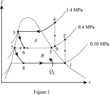
Show the T-s diagram for compression refrigeration cycle as in Figure (1).

From Figure (1), write the specific enthalpy at state 5 is equal to state 6 due to throttling process.
Here, specific enthalpy at state 5 and 6 is
From Figure (1), write the specific enthalpy at state 7 is equal to state 8 due to throttling process.
Here, specific enthalpy at state 7 and 8 is
Express the fraction of the refrigerant that evaporates as it is throttled to the flash chamber
Here, specific enthalpy at saturated vapor is
Conclusion:
Perform unit conversion of pressure at state 1 from
Refer Table A-12, “saturated refrigerant-134a-pressure table”, and write the properties corresponding to pressure at state 1
Here, specific entropy and enthalpy at state 1 is
Refer Table A-13, “superheated refrigerant 134a”, and write the specific enthalpy at state 2 corresponding to pressure at state 2 of
Write the formula of interpolation method of two variables.
Here, the variables denote by x and y is specific entropy at state 2 and specific enthalpy at state 2 respectively.
Show the specific enthalpy at state 2 corresponding to specific entropy as in Table (1).
|
Specific entropy at state 2 |
Specific enthalpy at state 2 |
| 0.9306 | 256.59 |
| 0.9519 | |
| 0.9628 | 265.88 |
Substitute
Thus, the specific enthalpy at state 2 is,
Perform unit conversion of pressure at state 3 from
Refer Table A-12, “saturated refrigerant-134a-pressure table”, and write the property corresponding to pressure at state 3
Perform unit conversion of pressure at state 5 from
Refer Table A-12, “saturated refrigerant-134a-pressure table”, and write the property corresponding to pressure at state 5
Here, specific enthalpy at saturated liquid is
Substitute
Refer Table A-12, “saturated refrigerant-134a-pressure table”, and write the property corresponding to pressure at state 8
Substitute
Refer Table A-12, “saturated refrigerant-134a-pressure table”, and write the specific enthalpy at evaporation and pressure of
Substitute
Hence, the fraction of the refrigerant that evaporates as it is throttled to the flash chamber is
(b)
The rate of heat removed from the refrigerated space.
(b)
Answer to Problem 53P
The rate of heat removed from the refrigerated space is
Explanation of Solution
Express the enthalpy at state 9 by using an energy balance on the mixing chamber.
Here, the rate of total energy entering the system is
Express the mass flow rate through the flash chamber.
Here, mass flow rate through condenser is
Express The rate of heat removed from the refrigerated space.
Conclusion:
Substitute
Substitute
Substitute
Hence, the rate of heat removed from the refrigerated space is
(c)
The coefficient of performance.
(c)
Answer to Problem 53P
The coefficient of performance is
Explanation of Solution
Express compressor work input per unit mass.
Express the coefficient of performance.
Express entropy at state 4.
Here, specific entropy at state 3 is
Conclusion:
Refer Table A-12, “saturated refrigerant-134a-pressure table”, and write the property corresponding to pressure at state 3
Here, specific entropy at saturated vapor is
Substitute
Refer Table A-13, “superheated refrigerant 134a”, and write the specific enthalpy at state 4 corresponding to pressure at state 4 of
Show the specific enthalpy at state 4 corresponding to specific entropy as in Table (2).
|
Specific entropy at state 4 |
Specific enthalpy at state 4 |
| 0.9389 | 285.47 |
| 0.9436 | |
| 0.9733 | 297.10 |
Use excels and substitute value from Table (2) in Equation (IV) to get,
Substitute
Substitute
Hence, the coefficient of performance is
Want to see more full solutions like this?
Chapter 11 Solutions
Thermodynamics: An Engineering Approach
- USE MATHLAB WITH CODES Estimate the damping ratio, stiffness, natural frequency, and mass of the SDOF system. Please use a MATHLAB with CODES and no negative damping ratio. Data Set 1:Time(s) Data Set 1:top1(g) Data Set 1:bottom(g)0 0.002593181 0.007262860.01 0.011367107528507709 -0.0015110660.02 0.007467585 -0.0058980290.029999999999999999 0.004542943 0.0028758970.040000000000000001 0.018678712689042091 -0.0019985060.050000000000000003 0.004542943 0.0009261360.059999999999999998 0.014779189431130886 -0.0068729090.070000000000000007 0.004055502 -0.0088226710.080000000000000002 0.008442465 -0.0015110660.089999999999999997 0.011854547366917134 -0.0039482670.10000000000000001 0.007467585 0.0058005390.11 0.004055502 0.0043382180.12 0.010392226334810257 0.0019010160.13 0.010392226334810257 -0.001998506% 0.14000000000000001 0.016728950301647186 0.0048256580.14999999999999999 0.007955025…arrow_forwardProvide an example of at least five features produced by a certain machining process (for example, a keyway to accommodate a key iarrow_forwardHow to draw a gam from the data of the subject's readings three times and difficulties in drawing a gam Material Name: Machinery Theory I'm a vehicle engineering student. Please describe details about gam in addition the law gam: 1-tangent cam with reciprocating roller follower. 2-circular arc cam with flat-faced follower.arrow_forward
- a 300n girl and an 400n boy stand on a 16m platform supported by posts A and B. The platform itself weighs 200N. What are the forces exerted by the supports on the platform?arrow_forwardC A cylindrical piece of steel 38 mm (1½ in.) in diameter is to be quenched in moderately agi- tated oil. Surface and center hardnesses must be at least 50 and 40 HRC, respectively. Which of the following alloys satisfy these requirements: 1040, 5140, 4340, 4140, and 8640? Justify your choice(s).arrow_forwardUsing the isothermal transformation diagram for a 1.13 wt% C steel alloy (Figure 10.39), determine the final microstructure (in terms of just the microconstituents present) of a small specimen that has been subjected to the following time-temperature treatments. In each case assume that the specimen begins at 920°C (1690°F) and that it has been held at this temperature long enough to have achieved a complete and homogeneous austenitic structure. (a) Rapidly cool to 250°C (480°F), hold for 103 s, then quench to room temperature. (b) Rapidly cool to 775°C (1430°F), hold for 500 s, then quench to room temperature. (c) Rapidly cool to 400°C (750°F), hold for 500 s, then quench to room temperature. (d) Rapidly cool to 700°C (1290°F), hold at this temperature for 105 s, then quench to room temperature. (e) Rapidly cool to 650°C (1200°F), hold at this temperature for 3 s, rapidly cool to 400°C (750°F), hold for 25 s, then quench to room temperature. (f) Rapidly cool to 350°C (660°F), hold for…arrow_forward
 Refrigeration and Air Conditioning Technology (Mi...Mechanical EngineeringISBN:9781305578296Author:John Tomczyk, Eugene Silberstein, Bill Whitman, Bill JohnsonPublisher:Cengage Learning
