Videos
Repeat Prob. 11–56 for a flash chamber pressure of 0.6 MPa.
(a)
The fraction of the refrigerant that evaporates as it is throttled to the flash chamber.
Answer to Problem 54P
The fraction of the refrigerant that evaporates as it is throttled to the flash chamber is
Explanation of Solution
Show the T-s diagram for compression refrigeration cycle as in Figure (1).
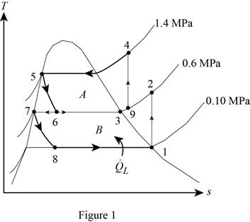
From Figure (1), write the specific enthalpy at state 5 is equal to state 6 due to throttling process.
Here, specific enthalpy at state 5 and 6 is
From Figure (1), write the specific enthalpy at state 7 is equal to state 8 due to throttling process.
Here, specific enthalpy at state 7 and 8 is
Express the fraction of the refrigerant that evaporates as it is throttled to the flash chamber
Here, specific enthalpy at saturated vapor is
Conclusion:
Perform unit conversion of pressure at state 1 from
Refer Table A-12, “saturated refrigerant-134a-pressure table”, and write the properties corresponding to pressure at state 1
Here, specific entropy and enthalpy at state 1 is
Refer Table A-13, “superheated refrigerant 134a”, and write the specific enthalpy at state 2 corresponding to pressure at state 2 of
Write the formula of interpolation method of two variables.
Here, the variables denote by x and y is specific entropy at state 2 and specific enthalpy at state 2 respectively.
Show the specific enthalpy at state 2 corresponding to specific entropy as in Table (1).
|
Specific entropy at state 2 |
Specific enthalpy at state 2 |
| 0.9500 | 270.83 |
| 0.9519 | |
| 0.9817 | 280.60 |
Substitute
Thus, the specific enthalpy at state 2 is,
Perform unit conversion of pressure at state 3 from
Refer Table A-12, “saturated refrigerant-134a-pressure table”, and write the property corresponding to pressure at state 3
Perform unit conversion of pressure at state 5 from
Refer Table A-12, “saturated refrigerant-134a-pressure table”, and write the property corresponding to pressure at state 5
Here, specific enthalpy at saturated liquid is
Substitute
Refer Table A-12, “saturated refrigerant-134a-pressure table”, and write the property corresponding to pressure at state 8
Substitute
Refer Table A-12, “saturated refrigerant-134a-pressure table”, and write the specific enthalpy at evaporation and pressure of
Substitute
Hence, the fraction of the refrigerant that evaporates as it is throttled to the flash chamber is
(b)
The rate of heat removed from the refrigerated space.
Answer to Problem 54P
The rate of heat removed from the refrigerated space is
Explanation of Solution
Express the enthalpy at state 9 by using an energy balance on the mixing chamber.
Here, the rate of total energy entering the system is
Express the mass flow rate through the flash chamber.
Here, mass flow rate through condenser is
Express The rate of heat removed from the refrigerated space.
Conclusion:
Substitute
Substitute
Substitute
Hence, the rate of heat removed from the refrigerated space is
(c)
The coefficient of performance.
Answer to Problem 54P
The coefficient of performance is
Explanation of Solution
Express compressor work input per unit mass.
Express the coefficient of performance.
Express entropy at state 4.
Here, specific entropy at state 3 is
Conclusion:
Refer Table A-12, “saturated refrigerant-134a-pressure table”, and write the property corresponding to pressure at state 3
Here, specific entropy at saturated vapor is
Substitute
Refer Table A-13, “superheated refrigerant 134a”, and write the specific enthalpy at state 4 corresponding to pressure at state 4 of
Show the specific enthalpy at state 4 corresponding to specific entropy as in Table (2).
|
Specific entropy at state 4 |
Specific enthalpy at state 4 |
| 0.9389 | 285.47 |
| 0.9444 | |
| 0.9733 | 297.10 |
Use excels and substitute value from Table (2) in Equation (IV) to get,
Substitute
Substitute
Hence, the coefficient of performance is
Want to see more full solutions like this?
Chapter 11 Solutions
Thermodynamics: An Engineering Approach


- The flow rate is 12.275 Liters/s and the diameter is 6.266 cm.arrow_forwardAn experimental setup is being built to study the flow in a large water main (i.e., a large pipe). The water main is expected to convey a discharge (Qp). The experimental tube will be built at a length scale of 1/20 of the actual water main. After building the experimental setup, the pressure drop per unit length in the model tube (APm/Lm) is measured. Problem (20): Given the value of APm/Lm [kPa/m], and assuming pressure coefficient similitude, calculate the drop in the pressure per unit length of the water main (APP/Lp) in [Pa/m]. Givens: AP M/L m = 590.637 kPa/m meen Answers: ( 1 ) 59.369 Pa/m ( 2 ) 73.83 Pa/m (3) 95.443 Pa/m ( 4 ) 44.444 Pa/m *******arrow_forwardFind the reaction force in y if Ain = 0.169 m^2, Aout = 0.143 m^2, p_in = 0.552 atm, Q = 0.367 m^3/s, α = 31.72 degrees. The pipe is flat on the ground so do not factor in weight of the pipe and fluid.arrow_forward
- Find the reaction force in x if Ain = 0.301 m^2, Aout = 0.177 m^2, p_in = 1.338 atm, Q = 0.669 m^3/s, and α = 37.183 degreesarrow_forwardProblem 5: Three-Force Equilibrium A structural connection at point O is in equilibrium under the action of three forces. • • . Member A applies a force of 9 kN vertically upward along the y-axis. Member B applies an unknown force F at the angle shown. Member C applies an unknown force T along its length at an angle shown. Determine the magnitudes of forces F and T required for equilibrium, assuming 0 = 90° y 9 kN Aarrow_forwardProblem 19: Determine the force in members HG, HE, and DE of the truss, and state if the members are in tension or compression. 4 ft K J I H G B C D E F -3 ft -3 ft 3 ft 3 ft 3 ft- 1500 lb 1500 lb 1500 lb 1500 lb 1500 lbarrow_forward
- Problem 14: Determine the reactions at the pin A, and the tension in cord. Neglect the thickness of the beam. F1=26kN F2 13 12 80° -2m 3marrow_forwardProblem 22: Determine the force in members GF, FC, and CD of the bridge truss and state if the members are in tension or compression. F 15 ft B D -40 ft 40 ft -40 ft 40 ft- 5 k 10 k 15 k 30 ft Earrow_forwardProblem 20: Determine the force in members BC, HC, and HG. After the truss is sectioned use a single equation of equilibrium for the calculation of each force. State if the members are in tension or compression. 5 kN 4 kN 4 kN 3 kN 2 kN B D E F 3 m -5 m- -5 m- 5 m 5 m-arrow_forward
- An experimental setup is being built to study the flow in a large water main (i.e., a large pipe). The water main is expected to convey a discharge (Qp). The experimental tube will be built at a length scale of 1/20 of the actual water main. After building the experimental setup, the pressure drop per unit length in the model tube (APm/Lm) is measured. Problem (19): Given the value of Qp [m³/s], and assuming Reynolds number similitude between the water main and experimental tube, calculate the flow rate in the model tube (Qm) in [lit/s]. = 30.015 m^3/sarrow_forwardProblem 11: The lamp has a weight of 15 lb and is supported by the six cords connected together as shown. Determine the tension in each cord and the angle 0 for equilibrium. Cord BC is horizontal. E 30° B 60° Aarrow_forwardProblem 10: If the bucket weighs 50 lb, determine the tension developed in each of the wires. B $30° 5 E D 130°arrow_forward
 Refrigeration and Air Conditioning Technology (Mi...Mechanical EngineeringISBN:9781305578296Author:John Tomczyk, Eugene Silberstein, Bill Whitman, Bill JohnsonPublisher:Cengage Learning