Videos
Consider a two-stage compression refrigeration system operating between the pressure limits of 1.4 and 0.12 MPa. The working fluid is refrigerant-134a. The refrigerant leaves the condenser as a saturated liquid and is throttled to a flash chamber operating at 0.5 MPa. Part of the refrigerant evaporates during this flashing process, and this vapor is mixed with the refrigerant leaving the low-pressure compressor. The mixture is then compressed to the condenser pressure by the high-pressure compressor. The liquid in the flash chamber is throttled to the evaporator pressure, and it cools the refrigerated space as it vaporizes in the evaporator. Assuming the refrigerant leaves the evaporator as saturated vapor and both compressors are isentropic, determine (a) the fraction of the refrigerant that evaporates as it is throttled to the flash chamber, (b) the amount of heat removed from the refrigerated space and the compressor work per unit mass of refrigerant flowing through the condenser, and (c) the coefficient of performance.
(a)
The fraction of the refrigerant that evaporates as it is throttled to the flash chamber.
Answer to Problem 113RP
The fraction of the refrigerant that evaporates as it is throttled to the flash chamber is
Explanation of Solution
Show the T-s diagram as in Figure (1).
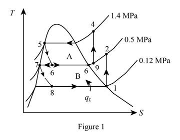
From Figure (1), write the specific enthalpy at state 5 is equal to state 6 due to throttling process.
Here, specific enthalpy at state 5 and 6 is
From Figure (1), write the specific enthalpy at state 7 is equal to state 8 due to throttling process.
Here, specific enthalpy at state 7 and 8 is
Express the fraction of the refrigerant that evaporates as it is throttled to the flash chamber
Here, specific enthalpy at saturated vapor is
Conclusion:
Perform unit conversion of pressure at state 1 from
Refer Table A-12, “saturated refrigerant-134a-pressure table”, and write the properties corresponding to pressure at state 1
Here, specific entropy and enthalpy at state 1 is
Refer Table A-13, “superheated refrigerant 134a”, and write the specific enthalpy at state 2 corresponding to pressure at state 2 of
Write the formula of interpolation method of two variables.
Here, the variables denote by x and y is specific entropy at state 2 and specific enthalpy at state 2 respectively.
Show the specific enthalpy at state 2 corresponding to specific entropy as in Table (1).
|
Specific entropy at state 2 |
Specific enthalpy at state 2 |
| 0.9384 | 263.48 |
| 0.94789 | |
| 0.9704 | 273.03 |
Substitute
Thus, the specific enthalpy at state 2 is,
Perform unit conversion of pressure at state 3 from
Refer Table A-12, “saturated refrigerant-134a-pressure table”, and write the property corresponding to pressure at state 3
Perform unit conversion of pressure at state 5 from
Refer Table A-12, “saturated refrigerant-134a-pressure table”, and write the property corresponding to pressure at state 5
Here, specific enthalpy at saturated liquid is
Substitute
Refer Table A-12, “saturated refrigerant-134a-pressure table”, and write the property corresponding to pressure at state 8
Substitute
Refer Table A-12, “saturated refrigerant-134a-pressure table”, and write the specific enthalpy at evaporation and pressure of
Substitute
Hence, the fraction of the refrigerant that evaporates as it is throttled to the flash chamber is
(b)
The amount of heat removed from the refrigerated space and the compressor work per unit mass of refrigerant flowing through the condenser.
Answer to Problem 113RP
The amount of heat removed from the refrigerated space is
Explanation of Solution
Express the enthalpy at state 9 by using an energy balance on the mixing chamber.
Here, the rate of total energy entering the system is
Express the amount of heat removed from the refrigerated space.
Express the compressor work per unit mass of refrigerant flowing through the condenser.
Conclusion:
Substitute
Refer Table A-13, “superheated refrigerant 134a”, and write the specific entropy at state 9 corresponding to pressure at state 9 of
Show the specific enthropy at state 9 corresponding to specific enthalpy as in Table (2).
|
Specific enthalpy at state 9 |
Specific entropy at state 9 |
| 263.48 | 0.9384 |
| 264.28 | |
| 273.03 | 0.9704 |
Use excels and tabulates the values of Table (2) in Equation (IV) to get,
Thus, the specific entropy at state 9 is,
Refer Table A-13, “superheated refrigerant 134a”, and write the specific enthalpy at state 4 corresponding to pressure at state 4 of
Substitute
Hence, the amount of heat removed from the refrigerated space is
Substitute
Hence, the compressor work per unit mass of refrigerant flowing through the condenser is
(c)
The coefficient of performance of the system.
Answer to Problem 113RP
The coefficient of performance of the system is
Explanation of Solution
Express the coefficient of performance of the system.
Conclusion:
Substitute
Hence, the coefficient of performance of the system is
Want to see more full solutions like this?
Chapter 11 Solutions
Thermodynamics: An Engineering Approach


- (read me)arrow_forward(read image)arrow_forwardQu. 13 What are the indices for the Direction 2 indicated by vector in the following sketch? Qu. 14 Determine the indices for the direction A and B shown in the following cubic unit cell. please show all work step by step from material engineeringarrow_forward
- The thin-walled open cross section shown is transmitting torque 7. The angle of twist ₁ per unit length of each leg can be determined separately using the equation 01 = 3Ti GLIC 3 where G is the shear modulus, ₁ is the angle of twist per unit length, T is torque, and L is the length of the median line. In this case, i = 1, 2, 3, and T; represents the torque in leg i. Assuming that the angle of twist per unit length for each leg is the same, show that T= Lic³ and Tmaz = G01 Cmax Consider a steel section with Tallow = 12.40 kpsi. C1 2 mm L1 20 mm C2 3 mm L2 30 mm C3 2 mm L3 25 mm Determine the torque transmitted by each leg and the torque transmitted by the entire section. The torque transmitted by the first leg is | N-m. The torque transmitted by the second leg is N-m. The torque transmitted by the third leg is N-m. The torque transmitted by the entire section is N-m.arrow_forwardPlease help, make sure it's to box out and make it clear what answers go where...arrow_forwardThe cylinder floats in the water and oil to the level shown. Determine the weight of the cylinder. (rho)o=910 kg/m^3arrow_forward
 Refrigeration and Air Conditioning Technology (Mi...Mechanical EngineeringISBN:9781305578296Author:John Tomczyk, Eugene Silberstein, Bill Whitman, Bill JohnsonPublisher:Cengage Learning