
Videos
a.
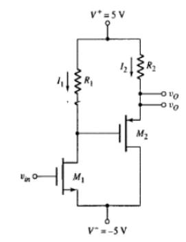
The value of the resistor R1 and R2 in a way that the dc value of the output voltage is 0.
a.
Answer to Problem 11.89P
The value of the resistances are:
Explanation of Solution
Given:
The circuit is given as:

The circuit parameters:
The drain current of
Considering the expression for drain current of
Hence, the value of the resistor
Evaluating the value of source gate voltage of
Considering the expression for the drain current of
Hence, the value of the resistor
b.
To sketch: The small signal equivalent circuit and then find the small signal transistor parameters.
b.
Explanation of Solution
Given:
The circuit is given as:

The circuit parameters:
Evaluating the value of trans-conductance
Substituting
Evaluating the value of trans-conductance of
Evaluating the value of the resistor
Evaluating the value of the resistor
c.
The small signal voltage gain.
c.
Answer to Problem 11.89P
The small signal gain of the circuit is -15.25V/V.
Explanation of Solution
Given:
The circuit is given as:
The circuit parameters:
Drawing the small signal equivalent model of the circuit:
Applying nodal analysis at the input node:
Referring to the above diagram:
Applying the nodal analysis at the output node:
Hence, the small signal gain of the circuit is -15.25V/V.
d.
The output resistance.
d.
Answer to Problem 11.89P
The value of the output resistance is
Explanation of Solution
Given:
The circuit is given as:

The circuit parameters:
Evaluating the output resistance
Substituting
Hence, the value of the output resistance is
Want to see more full solutions like this?
Chapter 11 Solutions
Microelectronics: Circuit Analysis and Design


- 4. Please find the stability margins from the following Bode diagrams. Bode Diagram Phase (deg) Magnitude (dB) 50 -100 -90 -135 -180 -270 10" 10° Frequency (rad/sec) 10'arrow_forward2. Please use asymptotes to draw the Bode diagrams of the following transfer function. Please label the axes to show the cut-off frequencies and key values on vertical axes and label each asymptote with its slope. G(s) s+10 s(s²+10s+100)arrow_forwardFind Voarrow_forward
- J. na ul-n-1) X (n) = na^ = na^ u(-(n+1)) (1-1+4)= 741-1 4[cn+1)] +1 * Z (^- 1-1 (n-1) a て why ✓ (n) Z , ༥(-༡) ur-n) Znxcm) -Zx X (n) (n-1) a auc-n) = X(n) ぞ 2-9³arrow_forwardTurn trip logic into boolean algebra gates logic?arrow_forwardFind the Z-transform including the region of convergence for the following function 12 (¹)" [u(n) – u(n − 5)] -arrow_forward
- Find the inverse Z-traform of X(z)= z 2 +z (z-0.125)³ (z-0.25)arrow_forwardA separately excited 6-kilowatt generator has a terminal voltage of 135V at no load. At full load, the terminal voltage is 120V with speed and field excitation unchanged. Armature resistance = = 0.25 ohm. A. What is the amount of voltage decrease caused by armature reaction and the voltage regulation?arrow_forwardJ. A sampling system can be set to adjust its sampling rate in 25 He steps. Considering the signal spectra pleted below, specify the minimum sampling rate setting for the signals: a)x(1) b)(1)+(1) 985)+20 0,09 0:00 0,0 106) 100) SORO -2501 250V (1500+501) 。 1500+50V 201 2500arrow_forward
 Introductory Circuit Analysis (13th Edition)Electrical EngineeringISBN:9780133923605Author:Robert L. BoylestadPublisher:PEARSON
 Delmar's Standard Textbook Of ElectricityElectrical EngineeringISBN:9781337900348Author:Stephen L. HermanPublisher:Cengage Learning
 Programmable Logic ControllersElectrical EngineeringISBN:9780073373843Author:Frank D. PetruzellaPublisher:McGraw-Hill Education
 Fundamentals of Electric CircuitsElectrical EngineeringISBN:9780078028229Author:Charles K Alexander, Matthew SadikuPublisher:McGraw-Hill Education
 Electric Circuits. (11th Edition)Electrical EngineeringISBN:9780134746968Author:James W. Nilsson, Susan RiedelPublisher:PEARSON
 Engineering ElectromagneticsElectrical EngineeringISBN:9780078028151Author:Hayt, William H. (william Hart), Jr, BUCK, John A.Publisher:Mcgraw-hill Education,