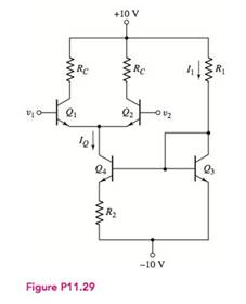
The transistor parameters for the circuit shown in Figure P 11.29 are β = 180 , V B E ( on ) = 0.7 V (except for Q 4 ), V A = ∞ for Q 1 and Q 2 , and V A = 100 V for Q 3 and Q 4 . (a) Determine R 1 and R 2 such that I 1 = 0.5 mA and I Q = 140 μ A . (b) Determine the common-mode input resistance. (c) For R C = 40 k Ω , determine the common-mode voltage gain.
The transistor parameters for the circuit shown in Figure P 11.29 are β = 180 , V B E ( on ) = 0.7 V (except for Q 4 ), V A = ∞ for Q 1 and Q 2 , and V A = 100 V for Q 3 and Q 4 . (a) Determine R 1 and R 2 such that I 1 = 0.5 mA and I Q = 140 μ A . (b) Determine the common-mode input resistance. (c) For R C = 40 k Ω , determine the common-mode voltage gain.
Solution Summary: The author explains the value of resistors in the current source circuit.
The transistor parameters for the circuit shown in Figure P 11.29 are
β
=
180
,
V
B
E
(
on
)
=
0.7
V
(except for
Q
4
),
V
A
=
∞
for
Q
1
and
Q
2
,
and
V
A
=
100
V
for
Q
3
and
Q
4
.
(a) Determine
R
1
and
R
2
such that
I
1
=
0.5
mA
and
I
Q
=
140
μ
A
.
(b) Determine the common-mode input resistance. (c) For
R
C
=
40
k
Ω
,
determine the common-mode voltage gain.
J. A sampling system can be set to adjust its sampling rate in 25 He steps. Considering the signal spectra
pleted below, specify the minimum sampling rate setting for the signals:
a)x(1)
b)(1)+(1)
985)+20
0,09
0:00
0,0
106)
100)
SORO
-2501
250V
(1500+501)
。 1500+50V
201
2500
1. For this problem, state your answers to 4 significant figures.
(1)For the message signal shown below, sketch the phase-meduced
form
and 4-5/N rad V. Specify values of the miniman & maximum instantaneous frequencies in He
(b) Find the approximate bandwidth of the phase-modulaud signal, assuming that the effective handwidth of
the message is equal to its 4th harmonic frequency
(N-2015
101
2x10' 159-
4. For the filter shown below, with an input signal whose PSD by 20
(4) Find the
pet power
in
(b) Find the trafor
(4) Find the power spel de
PSD) of 4 put signat
(d) Find the talutput power of the signal
a
C-58-18
-
Need a deep-dive on the concept behind this application? Look no further. Learn more about this topic, electrical-engineering and related others by exploring similar questions and additional content below.


 Power System Analysis and Design (MindTap Course ...Electrical EngineeringISBN:9781305632134Author:J. Duncan Glover, Thomas Overbye, Mulukutla S. SarmaPublisher:Cengage Learning
 EBK ELECTRICAL WIRING RESIDENTIALElectrical EngineeringISBN:9781337516549Author:SimmonsPublisher:CENGAGE LEARNING - CONSIGNMENT
 Electricity for Refrigeration, Heating, and Air C...Mechanical EngineeringISBN:9781337399128Author:Russell E. SmithPublisher:Cengage Learning
 Delmar's Standard Textbook Of ElectricityElectrical EngineeringISBN:9781337900348Author:Stephen L. HermanPublisher:Cengage Learning