A built-Lip I-section steel beam with channels attached to the flanges (sec Figure part a) is simply supported at the ends. Two equal and oppositely directed bending moments I/2, act at the ends of the beam, so the beam is in pure bending. The moments act in plane mm. which is oriented at an angle a to (a) Determine the orientation of the neutral axis and calculate the maximum (ensile stress on till due to the moments Ma. (b) Repeat pan (a) if (he channels now have their flanges pointing away from the beam flange, as shown in the figure part b. Data for the beam are S 6 x 12.5 section with C 4 x 5.4 sections attached to the Hanges, .V/2— 45 kip-in., and a = 40°. See Tables F-2(a) and F-3(a) of Appendix F l or the dimensions and properlies of the S and shapes.
A built-Lip I-section steel beam with channels attached to the flanges (sec Figure part a) is simply supported at the ends. Two equal and oppositely directed bending moments I/2, act at the ends of the beam, so the beam is in pure bending. The moments act in plane mm. which is oriented at an angle a to (a) Determine the orientation of the neutral axis and calculate the maximum (ensile stress on till due to the moments Ma. (b) Repeat pan (a) if (he channels now have their flanges pointing away from the beam flange, as shown in the figure part b. Data for the beam are S 6 x 12.5 section with C 4 x 5.4 sections attached to the Hanges, .V/2— 45 kip-in., and a = 40°. See Tables F-2(a) and F-3(a) of Appendix F l or the dimensions and properlies of the S and shapes.
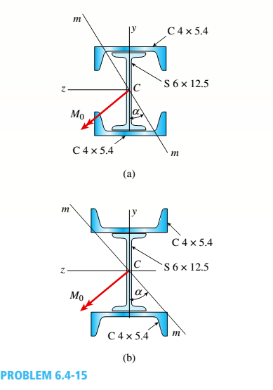
A built-Lip I-section steel beam with channels attached to the flanges (sec Figure part a) is simply supported at the ends. Two equal and oppositely directed bending moments I/2, act at the ends of the beam, so the beam is in pure bending. The moments act in plane mm. which is oriented at an angle a to
(a)
Determine the orientation of the neutral axis and calculate the maximum (ensile stress on till due to the moments Ma.
(b)
Repeat pan (a) if (he channels now have their flanges pointing away from the beam flange, as shown in the figure part b. Data for the beam are S 6 x 12.5 section with C 4 x 5.4 sections attached to the Hanges, .V/2— 45 kip-in., and a = 40°. See Tables F-2(a) and F-3(a) of Appendix F l or the dimensions and properlies of the S and shapes.
Consider a standard piston engine . Draw a free body diagram of the piston. Then:a) For an A SI engine with a 100 mm bore at an instantaneous cylinder pressure of 42 bar i. Calculate the level of the combustion gas loading force on the wrist pin in kN. b) Repeat this calculationfor a forced-induction Diesel engine with a 145 mm boreat a cylinder pressure of 115 bar
A punch press with flywheel adequate to minimize speed fluctuation produces 120 punching strokes per minute, each providing an average force of 2000 N over a stroke of 50 mm. The press is driven through a gear reducer by a shaft rotating 200 rpm. Overall efficiency is 80%. a) What power (W) is transmitted through the shaft? b) What average torque is applied to the shaft?
1.58 The crankshaft of a single-cylinder air compressor rotates 1800 rpm. The piston area is 2000 mm2 and the piston stroke is 50 mm. Assume a simple “idealized” case where the average gas pressure acting on the piston during the compression stroke is 1 MPa, and pressure during the intake stroke is negligible. The compressor is 80% efficient. A flywheel provides adequate control of the speed fluctuation. a) What motor power (kW) is required to drive the crankshaft? b) What torque is transmitted through the crankshaft?
Need a deep-dive on the concept behind this application? Look no further. Learn more about this topic, mechanical-engineering and related others by exploring similar questions and additional content below.


 Mechanics of Materials (MindTap Course List)Mechanical EngineeringISBN:9781337093347Author:Barry J. Goodno, James M. GerePublisher:Cengage Learning