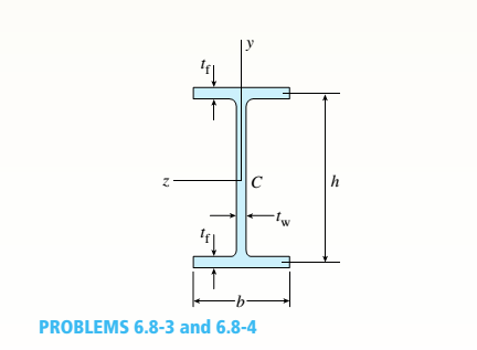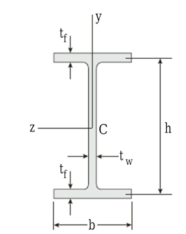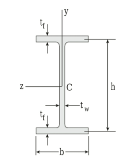
A beam of wide-flange shape, W 8 x 28, has the cross section shown in the figure. The dimensions are b = 6.54 in., h = 8.06 in., fw = 0.285 in., and tf = 0.465 in.. The loads on the beam produce a shear force V = 7.5 kips at the cross section under consideration.
- Use center line dimensions to calculate the maximum shear stress raiaxin the web of the beam.

a.
The maximum shear stress
Answer to Problem 6.8.3P
The maximum shear stress
Explanation of Solution
Figure :

Given:
The section
Concept Used:
Annuity problem requires the use of the moment of inertia equation as follows:
Here,
Annuity problem requires the use of the maximum shear stress equation as follows:
Here,
Calculation:
As per the given problem
Annuity problem requires the use of this formula based on centerline dimensions
Substitute these values in the formula
Annuity problem requires the use of this formula
Substitute these values in the formula
Conclusion:
The maximum shear stress
b.
The maximum shear stress
Answer to Problem 6.8.3P
The maximum shear stress
Explanation of Solution
Figure:

Given:
The section
Concept Used:
Annuity problem requires the use of the equation as follows:
Here,
Annuity problem requires the use of the moment of inertia equation as follows:
Here,
Annuity problem requires the use of the maximum shear stress equation in the web as follows:
Here,
Calculation:
Based on more exact analysis As per the given problem
Annuity problem requires the use of this formula:
Substitute these values in the formula
Annuity problem requires the use of this formula
Substitute these values in the formula:
Annuity problem requires the use of this formula
Substitute these values in the formula
Annuity problem requires the use of this formula
Substitute these values in the formula
Conclusion:
The maximum shear stress
Want to see more full solutions like this?
Chapter 6 Solutions
Mechanics of Materials (MindTap Course List)
- please read everything properly... Take 3 4 5 hrs but solve full accurate drawing on bond paper don't use chat gpt etc okk.... Not old solutions just new solvearrow_forwardplease box out or highlight all the answersarrow_forwardWhat are some ways Historical Data can be used and applied to an estimate?arrow_forward
- Problem 1. Rod OAB is rotating counterclockwise with the constant angular velocity of 5 rad/s. In the position shown, collar P is sliding toward A with the constant speed of 0.8 m/s relative to the rod. Find the velocity of P and the acceleration of P. y B 3 P 300 mm A - Answer: Up = -0.861 − 0.48ĵ™; ā₂ = 4.8î −1.1ĵ marrow_forwardA bent tube is attached to a wall with brackets as shown. . A force of F = 980 lb is applied to the end of the tube with direction indicated by the dimensions in the figure. a.) Determine the force vector F in Cartesian components. → → b.) Resolve the force vector F into vector components parallel and perpendicular to the position vector rDA. Express each of these vectors in Cartesian components. 2013 Michael Swanbom cc 10 BY NC SA g x B A א Z FK с кая b Values for dimensions on the figure are given in the table below. Note the figure may not be to scale. Be sure to align your cartesian unit vectors with the coordinate axes shown in the figure. Variable Value a 8 in 12 in с 15 in 36 in h 23 in g 28 in a. F = b. FDA = = ( + k) lb k) lb FIDA = 2 + k) lbarrow_forwardProblem 4. Part 1 100 mm C @ PROBLEM 15.160 Pin P slides in the circular slot cut in the plate shown at a constant relative speed u = 500 mm/s. Assuming that at the instant shown the angular velocity of the plate is 6 rad/s and is increasing at the rate of 20 rad/s², determine the acceleration of pin P when = 90°. 150 mm is NOT zero. Answer: a = 3.4î −15.1ĵ m/s² ) P (Hint: u is a constant number, which means that the tangential component of F is zero. However, the normal component of Part2. When 0 = 120°, u = 600 mm/s and is increasing at the rate of 30mm/s², determine the acceleration of pin P.arrow_forward
- Problem 5. Disk D of the Geneva mechanism rotates with constant counterclockwise angular velocity wD = 10 rad/s. At the instant when & = 150º, determine (a) the angular velocity of disk S, and (b) the velocity of pin P relative to disk S. (c). the angular acceleration of S. Disk S R=50 mm =135° |1=√ER- Disk D Partial answers: Ō = -4.08 Â rad/s ā¸ = -233 k rad/s²arrow_forwardProblem 3. In the figure below, point A protrudes from link AB and slides in the rod OC. Rod OC is rotating with angular velocity woc = 2 rad/s and aoc = 3 rad/s² in the directions shown. Find the following, remembering to clearly define your axes and the rate of rotation of the frame. a. The angular velocity of link AB and the velocity of A relative to rod OC. m (Answers: @AB is 2.9 rad/s CCW, rxy = .58! toward C) S b. The angular acceleration of link AB and the acceleration of A relative to rod OC. Answers: αAB = 7.12 rad/s² CCW, r = 6.3 m ܐܨ toward C. B C A 30° Фос 400 mm OA=500 mm docarrow_forwardProblem 2. 6 m 30° B PROBLEM 15.164 At the instant shown the length of the boom AB is being decreased at the constant rate of 0.2 m/s and the boom is being lowered at the constant rate of 0.08 rad/s. Determine (a) the velocity of Point B, (b) the acceleration of Point B. Partial answer: a = −0.049î +0.009ĵ m/s²arrow_forward
- A crate is hung by three ropes attached to a steel ring at A such that the top surface is parallel to the xy plane. Point A is located at a height of h = 121.92 cm above the top of the crate directly over the geometric center of the top surface. Use the given dimensions from the table below to perform the following calculations: →> a.) Determine the position vector IAD that describes rope AD. b.) Compute the unit vector cд that points from point C to point A. c.) If rope AB carries a tension force of magnitude FT = 760 → N, determine the force vector FT that expresses how this force acts on point A. Express each vector in Cartesian components to three significant figures. 2013 Michael Swanbom ↑z BY NC SA b x B У a D Values for dimensions on the figure are given in the following table. Note the figure may not be to scale. Be sure to align your cartesian unit vectors with the coordinate axes shown in the figure. Variable Value a 101.6 cm b 124.46 cm с 38.71 cm a. rдD = + b. ÛCA c. FT= =…arrow_forwardF3 N< Ꮎ 2 F2 -Y F1 There are 3 forces acting on the eye bolt. Force F1 acts on the XY plane has a magnitude of 536 lbf, and the angle of 0 = 38°. Force F2 acts on the YZ plane has a magnitude of 651 lbf, and the angle = 41°. Force F3 has a magnitude of 256 lb, and coordinate. = f direction angles of a 71°, B = 115°, and y = 33°. Determine the resultant force on the eye bolt. FR = ( + k) lbf FR magnitude: FR coordinate direction angle a: deg FR coordinate direction angle ẞ`: deg FR coordinate direction angle y: deg lbfarrow_forwardBall joints connect the ends of each of the struts as shown. The resulting structure supports a force of F = 1925 N which lies in the xz plane. a.) Determine the angle (in degrees) between strut AD and strut AC. b.) Determine the dimension g such that the force Fis →> perpendicular to гAC. 2013 Michael Swanbom CC BY NC SA B b C h/ L 不 g F ୮ d y LLC Values for dimensions on the figure are given in the table below. Note the figure may not be to scale. Be sure to align your cartesian unit vectors with the coordinate axes shown in the figure. Variable Value a 4.8 cm b 13.4 cm C 11.6 cm d 10.4 cm h 4.4 cm k 14.8 cm a. The angle between strut AD and strut AC is b. The dimension g is deg. cm.arrow_forward
 Mechanics of Materials (MindTap Course List)Mechanical EngineeringISBN:9781337093347Author:Barry J. Goodno, James M. GerePublisher:Cengage Learning
