
Videos
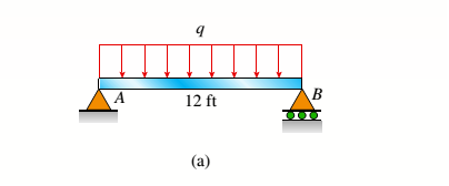
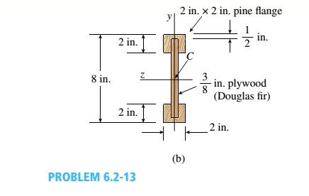
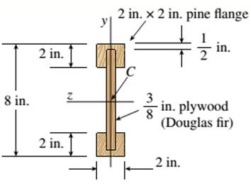
A simply supported wooden I-beam with a 12-ft span supports a distributed load of intensity q = 90 lb/ft over its length (see figure part a). The beam is constructed with a web of Douglas-fir plywood and flanges of pine glued to the web, as shown in the figure part b. The plywood is 3/8 in. thick: the flanges are 2 in, × 2 in, (actual size). The modulus of elasticity for the plywood is 1,600,000 psi and for the pine is 1,200,000 psL
- Calculate the maximum bending stresses in the pine flanges and in the plywood web.
a.
The bending stress that is maximum in the plywood web and pine flanges
Answer to Problem 6.2.13P
Bending Stress Maximum for plywood
Bending Stress Maximum for pine
Explanation of Solution
Given:
The given figure
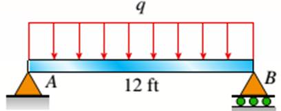
The I beam that is wooden has the span of 12 ft over its length supporting a distributed intensity load q=90lb/ft. The beam is made of Douglas fir plywood web and pine flanges with the plywood having a thickness of 3/8 in and that of flanges 2in.*2in. The elasticity modulus of the plywood is 1,600,000psi and for pine it is 1,200,000psi.
Concept Used:
Bending Stress Maximum for plywood,
Where,
Calculation:
Bending moment maximum is given as
Substituting the values we have,
Plywood moment of inertia is given as,
Pine moment of inertia is given as,
Bending Stress Maximum for plywood,
Bending Stress Maximum for pine,
Conclusion:
Thus, the bending stress that is maximum in the plywood web and pine flanges is given by equating the maximum bending movement
b.
The qmax with 1600psi maximum stress in flanges and for web being 1200psi.
Answer to Problem 6.2.13P
Explanation of Solution
Given:
The given figure:
The I beam that is wooden has the span of 12 ft over its length supporting a distributed intensity load q=90lb/ft. The beam is made of Douglas fir plywood web and pine flanges with the plywood having a thickness of 3/8 in and that of flanges 2in.*2in. The elasticity modulus of the plywood is 1,600,000psi and for pine it is 1,200,000psi.
Concept Used:
Web maximum stress,
Where,
Calculation:
Maximum stress Maximum for Web,
Substituting the values we have,
Maximum stress Maximum for flange,
Substituting the values we have,
Bending moment that is maximum,
Maximum uniform load distributed is given as,
Conclusion:
Thus, the qmax with 1600psi maximum stress in flanges and for web being 1200psi is given by the equation of maximum load.
Want to see more full solutions like this?
Chapter 6 Solutions
Mechanics of Materials (MindTap Course List)


- Determine the distance between the two automobiles 2 s after A has passed through the intersection.arrow_forwardA box barge 65 m long and 12 m wide floats at a draught of5.5 m in sea water. Calculate:(a) the displacement of the barge,(b) its draught in fresh waterarrow_forwardwhat is the angle of the velocity of block B? velocity is 7.46 in/s Determine the acceleration and angle of block B. (Round the acceleration value to three decimal places.)arrow_forward
- Determine the relative velocity of B with respect to A.arrow_forwardGenerate the kinematic diagram of the following mechanism. Then, draw their graphs and calculate their degrees of freedom (DoF) using Gruebler's formula.arrow_forwardAn elastic bar of length L = 1m and cross section A = 1cm2 spins with angular velocity ω about an axis, as shown in the figure below. The radial acceleration at a generic point x along the bar is a(x) = ω2x, where ω= 100rad/s is the angular velocity. The bar is pinned on the rotation axis at x = 0. A mass M = 1kg is attached to the right end of the bar. Due to the radial acceleration, the bar stretches along x with displacement function u(x). The displacement u(x) solves the BVP (strong form) sketched below: d dx (σ(x)) + ρa(x) = 0 PDE σ(x) = E du dx Hooke’s law (1) u(0) =?? essential BC σ(L) =?? natural BC where σ(x) is the axial stress in the rod, ρ= 2700kg /m3 is the mass density, and E = 70GPa is the Young’s modulus 1. Define appropriate BCs for the strong BVP 2. Find the solution of the strong BVP analytically 3. Derive the weak form of the BVP.arrow_forward
- Gruebler's formula for the following mechanism?arrow_forwardw/I - | العنوان I need a detailed drawing with explanation SOLL эт 4 حكا The guide vane angle of a reaction turbine (Francis type make 20° with the tangent. The moving blade angle at entry is 120°. The external diameter of runner is 450 mm and the internal diameter is 300 mm. Runner width at entry is 62.5mm and at exit 100mm. Calculate the blade angle at exit for radial discharge. 96252 -20125 750 ×2.01arrow_forwardCompressor Selection: (Q1) While a manufacturing cell is running, the calculated flow rate of air into a compressor is 40 SCFM. Which compressor from this list should be selected? A. A compressor that uses 80 SCFM B. A compressor that uses 40 SCFM C. A compressor that delivers 80 SCFM D. A compressor that delivers 40 SCFMarrow_forward
- SCFM Calculation: (Q1) A pneumatic system running a manufacturing cell works on 80 psi and requires a flow rate of 10 CFM to operate. A compressor must be selected to run the cell. Calculate the amount of air going into the compressor to run this cell. (Hint: This will be in SCFM) Accurate to two decimals. Do not write the unit.arrow_forward: +00 العنوان >scóny : + 개 العنوان I need a actanicu urawing wit д い Ants nation Taxi pu +9635. The guide vane angle of a reaction turbine (Francis type make 20° with the tangent. The moving blade angle at entry is 120°. The external diameter of runner is 450 mm and the internal diameter is 300 mm. Runner width at entry is 62.5mm and at exit 100mm. Calculate the blade angle t exit for radial discharge. ۲/۱ = 44 985arrow_forward:+B العنوان I need a actanicu urawing with Car nation The guide vane angle of a reaction turbine (Francis type make 20° with the tangent. The moving blade angle at entry is 120° The external diameter of runner is 450 mm and the internal diameter is 300 mm. Runner width at entry is 62.5mm and at exit 100mm. Calculate the blade angle at exit for radial discharge.arrow_forward
 Mechanics of Materials (MindTap Course List)Mechanical EngineeringISBN:9781337093347Author:Barry J. Goodno, James M. GerePublisher:Cengage Learning