
Videos
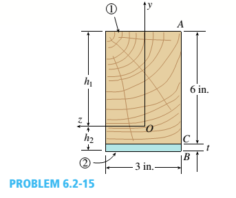
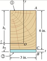
-15 A composite beam is constructed froma wood beam (3 in. x 6 in.) and a steel plate (3 in, wide). The wood and the steel are securely fastened to act as a single beam. The beam is subjected to a positive bending moment M. = 75 kip-in. Calculate the required thickness of the steel plate based on the following limit states:
- Allowable compressive stress in the wood = 2 ksi
- Allowable tensile stress in the wood = 2 ksi
- Allowable tensile stress in the steel plate = 16 ksi Assume that Ew= 1,500 ksi and es= 30,000 ksi.
a.
The thickness required for the steel plate.
Answer to Problem 6.2.15P
The thickness required for the steel plate
Explanation of Solution
Given:
The given figure

The wooden beam of 3in.*6in. and steel plate with wide 3in. forms the beam. The positive bending moment is given as
Concept Used:
Normal stress that is maximum for steel,
Where,
Calculation:
Neutral axis location at the lower end is given as,
Substituting the values we have,
From the top the neutral axis distance is given as,
The wooden section moment of inertia is given as,
The steel section moment of inertia is given as,
The normal stress that is maximum in the section of steel,
Conclusion:
Thus, the thickness required for the steel plate is calculated by equating bending movement, wood inertia, steel inertia, steel inertia, wood modulus elasticity, steel modulus elasticity and height.
b.
The thickness required for the steel plate.
Answer to Problem 6.2.15P
The thickness required for the steel plate
Explanation of Solution
Given:
The given figure:

The wooden beam of 3in.*6in. and steel plate with wide 3in. forms the beam. The positive bending moment is given as
Concept Used:
Wood maximum stress of top part is given as,
Where,
Calculation:
Normal Maximum stress for Wood at the top,
Substituting the values we have,
Conclusion:
Thus, the thickness required for the steel plate is calculated by wood modulus elasticity, steel modulus elasticity and height.
c.
The thickness required for the steel plate.
Answer to Problem 6.2.15P
Explanation of Solution
Given:
The given figure:
The wooden beam of 3in.*6in. and steel plate with wide 3in. forms the beam. The positive bending moment is given as
Concept Used:
Wood maximum stress of bottom part is given as,,
Where,
Calculation:
Maximum stress Maximum for Wood at the bottom,
Substituting the values we have,
Conclusion:
Thus, the thickness required for the steel plate is calculated by maximum stress, steel inertia moment, wood inertia moment , wood modulus elasticity, steel modulus elasticity.
Want to see more full solutions like this?
Chapter 6 Solutions
Mechanics of Materials (MindTap Course List)


- Note: Please provide a clear, step-by-step simplified handwritten working out (no explanations!), ensuring it is done without any AI involvement. I require an expert-level answer, and I will assess and rate based on the quality and accuracy of your work and refer to the provided image for more clarity. Make sure to double-check everything for correctness before submitting appreciate your time and effort!. Question:arrow_forward4. Block A and B are two different pieces of wood. Determine the minimum dimension for "a", if the shear stress of the wood is 50Mpa. The thickness of the wood is 30cm. 600N Aarrow_forward1. Determine the reaction force at A. 60 kN 5 B 1 m 1 m- -1 m 4 3 m 30 kN marrow_forward
- Find the Laplace Transform of the following functions 1) f() cos(ar) Ans. F(s)=7 2ws 2) f() sin(at) Ans. F(s)= s² + a² 3) f(r)-rcosh(at) Ans. F(s)= 2as 4)(t)=sin(at) Ans. F(s)= 2 5) f(1) = 2te' Ans. F(s)= (S-1) 5+2 6) (1) e cos() Ans. F(s) = (+2)+1 7) (1) (Acostẞr)+ Bsin(Br)) Ans. F(s)- A(s+a)+BB (s+a)+B 8) f()-(-)() Ans. F(s)= 9)(1)(1) Ans. F(s): 10) f(r),()sin() Ans. F(s): 11) 2 k 12) 0 13) 0 70 ㄷ.. a 2a 3a 4a 2 3 4 14) f(1)=1, 0<1<2 15) (1) Ksin(t) 0arrow_forward2. Determine the average normal stress developed in rod AB. The mass is 50kg and the diameter of the rod AB is 8mm. B 8 mmarrow_forward2.64 A 2.75-kN tensile load is applied to a test coupon made from 1.6-mm flat steel plate (E = 200 GPa, v = 0.30). Determine the resulting change in (a) the 50-mm gage length, (b) the width of portion AB of the test coupon, (c) the thickness of portion AB, (d) the cross-sectional area of portion AB. 2.75 kN A 12 mm 50 mm B 2.75 kNarrow_forwardProcedure:1- Cartesian system, 2(D)/(3)D,type of support2- Free body diagram3 - Find the support reactions4- If you find a negativenumber then flip the force5- Find the internal force3D\sum Fx=0\sum Fy=0\sum Fz=0\sum Mx=0\sum My=0\Sigma Mz=02D\Sigma Fx=0\Sigma Fy=0\Sigma Mz=05- Use method of sectionand cut the elementwhere you want to findthe internal force andkeep either side of thesectionarrow_forward3. The design of a pump and pipe system has been completed, except for the valves. The system is used to transpor10t water at 120°F through 2 nom sch 40 commercial steel pipe at a required flow rate of 85 gpm. Without the valves, the pump selected has the capability to overcome an additional 18 psi of pressure drop due to the valves and still provide the required flow rate. The pipe/valve joints are threaded. Determine how many 2-inch globe valves can be installed in this pump and pipe system.arrow_forward4. Figure 1 shows a pump and pipe network being used to transport heptane at 120°F to a large, elevated, closed storage tank. The tank is pressurized and maintained at 18 psia. The volumetric flow rate of the heptane is 500 gpm. a. Specify the nominal diameter of the check valve. b. Determine the pump discharge pressure required (psia) to move the heptane through the discharge pipe. Plank = 18 psia Liquid level Large pressurized storage tank 40 ft All pipes are 6-nom sch 40 commercial steel Standard 90° elbows and 180° bend Total length of straight pipe = 115 ft Class 300 swing check valve INH Pump Figure 1: Pressurized storage tank systemarrow_forward2. In a particular section of a fluid system, a 30% ethylene glycol mixture is flowing through a 6- nom xs cast iron pipe at a temperature of 0°C. In this section of piping, the velocity must be maintained in the range 1.5 m/sarrow_forward1. Steam leaves the boiler of a power plant at 5 MPa, 500°C as shown in the following figure. As the steam passes to the turbine, the temperature drops to 496°C before it enters the turbine due to a heat loss through the pipe's insulation. The pressure drop in the pipe connecting the boiler to the turbine is negligible. The steam then passes through an adiabatic turbine and exits at 10 kPa. The turbine has an isentropic efficiency of 85% and is delivering 1000 MW of power. Determine the following. P = 5 MPa T₁ = 500°C Boiler P₁₂ =5 MPa Τ =496°C 7 = 85% W = 1,000 MW P=1 atm To=25°C Turbine 3+ P = 10 kPa a. The heat transfer rate from the pipe connecting the boiler to the turbine (in MW) b. The change in flow exergy rate as the steam flows through the pipe (MW). This represents exergy that is lost to the environment and unavailable for power delivery. Comment on the magnitude of this exergy loss compared to the power delivered by the turbine. What factor(s) would warrant better…arrow_forwardAn aluminum rod of length L = 1m has mass density p = 2700 kg and Young's modulus E = 70 GPa. The rod is fixed at both ends. The exact natural eigenfrequencies of the rod are wexact E = √ ρ for n=1,2,3,. . . . 1. What is the minimum number of linear elements necessary to determine the fundamental frequency w₁ of the system? Discretize the rod in that many elements of equal length, assemble the global system of equations KU = w² MU, and find the fundamental frequency w₁. Compute the relative error e₁ = (w1 - wexact) /w exact Sketch the fundamental mode of vibration. 2. Use COMSOL to solve the same problem. Show the steps necessary to find the fundamental frequency and mode of the rod. What is the relative error using linear elements and a normal mesh?arrow_forwardarrow_back_iosSEE MORE QUESTIONSarrow_forward_iosRecommended textbooks for you
 Mechanics of Materials (MindTap Course List)Mechanical EngineeringISBN:9781337093347Author:Barry J. Goodno, James M. GerePublisher:Cengage Learning
Mechanics of Materials (MindTap Course List)Mechanical EngineeringISBN:9781337093347Author:Barry J. Goodno, James M. GerePublisher:Cengage Learning