The circuit parameters for the circuit in Figure 6.3 are V C C = 3.3 V , V B B = 0.850 V , R B = 180 kΩ , and R C = 15 kΩ . The transistor parameters are β = 120 and V B E (on) = 0.7 V . (a) Determine the Q −point values I C Q and V C E Q . (b) Find the small−signal hybrid− π parameters g m and r π . (c) Calculate the small−signal voltage gain. (Ans. (a) I C Q =0 .1mA , V C E Q = 1.8 V ; (b) g m = 3.846 mA/V , r π = 31.2 kΩ ; (c) A υ = − 8.52 ).
The circuit parameters for the circuit in Figure 6.3 are V C C = 3.3 V , V B B = 0.850 V , R B = 180 kΩ , and R C = 15 kΩ . The transistor parameters are β = 120 and V B E (on) = 0.7 V . (a) Determine the Q −point values I C Q and V C E Q . (b) Find the small−signal hybrid− π parameters g m and r π . (c) Calculate the small−signal voltage gain. (Ans. (a) I C Q =0 .1mA , V C E Q = 1.8 V ; (b) g m = 3.846 mA/V , r π = 31.2 kΩ ; (c) A υ = − 8.52 ).
The circuit parameters for the circuit in Figure 6.3 are
V
C
C
=
3.3
V
,
V
B
B
=
0.850
V
,
R
B
=
180
kΩ
, and
R
C
=
15
kΩ
. The transistor parameters are
β
=
120
and
V
B
E
(on)
=
0.7
V
. (a) Determine the Q−point values
I
C
Q
and
V
C
E
Q
. (b) Find the small−signal hybrid−
π
parameters
g
m
and
r
π
. (c) Calculate the small−signal voltage gain. (Ans. (a)
I
C
Q
=0
.1mA
,
V
C
E
Q
=
1.8
V
; (b)
g
m
=
3.846
mA/V
,
r
π
=
31.2
kΩ
; (c)
A
υ
=
−
8.52
).
(a)
Expert Solution
To determine
The quiescent collector current ICQ and the Q -point value VCEQ for the given transistor.
Answer to Problem 6.1EP
The quiescent collector current ICQ is 0.1 mA and Q -point VCEQ is 1.8 V .
Explanation of Solution
Given:
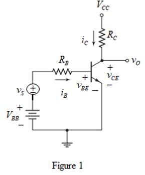
The circuit for common emitter is shown in Figure 1.
The circuit parameters for the transistor circuit shown in Figure 1 are as follows:
VCC=3.3 VRC=15 kΩRB=180 kΩVBE(on)=0.7 VVBB=0.85 V
The value of current gain β is 120 .
Concept used:
The expression for quiescent collector current is written below:
ICQ=βIBQ ...... (1)
The expression for quiescent value VCEQ is written below.
VCEQ=VCC−ICQRC ...... (2)
Calculation:
From DC analysis the ac voltage source is reduced to zero and the equation can be written as,
IBQ=VBB−VB(on)RB ...... (3)
Substitute 0.85 for VBB , 0.7 for VB(on) and 180×103 for RB in equation (3).
IBQ=0.85−0.7180×103=11200 mA
Substitute 120 for β and 11200 for IBQ in equation (1).
ICQ=120⋅11200 mA=110 mA=0.1 mA
Therefore, the quiescent collector current ICQ is 0.1 mA .
Substitute 3.3 for VCC , 0.1×10⁻³ for ICQ and 15×103 for RC in equation (2).
VCEQ=3.3−(0.1×10⁻³)(15×103)=3.3−1.5=1.8 V
Therefore, the Q -point VCEQ is 1.8 V .
Conclusion:
Thus, the quiescent collector current ICQ is 0.1 mA and Q -point VCEQ is 1.8 V .
(b)
Expert Solution
To determine
The transconductance gm and the diffusion resistance rπ for small signal analysis.
Answer to Problem 6.1EP
The transconductance gm is 3.846mA/V and the diffusion resistance rπ is 31.2 kΩ .
Explanation of Solution
Concept used:
The expression for transconductance gm is written below.
gm=ICQVT ...... (4)
Here, VT is thermal voltage and its value is 26 mV .
The expression for diffusion resistance is written below.
rπ=βVTICQ ...... (5)
Calculation:
Substitute 0.1×10⁻³ for ICQ and 26×10−3 for VT in equation (4).
gm=0.1×10−326×10−3=3.846mA/V
Therefore, the transconductance gm is 3.846mA/V .
Substitute 120 for β , 26×10−3 for VT and 0.1×10⁻³ for ICQ in equation (5).
rπ=120(26×10−3)0.1×10−3=31.2×10³Ω
Therefore, the diffusion resistance rπ is 31.2 kΩ .
Conclusion:
Thus, the transconductance gm is 3.846mA/V and the diffusion resistance rπ is 31.2 kΩ .
(c)
Expert Solution
To determine
The value of small signal voltage gain Av .
Answer to Problem 6.1EP
The value of small signal voltage gain Av is −8.52 .
Explanation of Solution
Concept used:
The expression for small signal voltage gain Av is written below.
Av=−(gmRC)⋅(rπrπ+RB) ...... (6)
Calculation:
Substitute 3.846 for gm , 15 for RC , 31.2 for rπ and 180 for RB in equation (6).
Av=−[(3.846)(15)]⋅(31.231.2+180)≈−8.52
Therefore, the voltage gain Av is −8.52 .
Conclusion:
Thus, the value of small signal voltage gain Av is −8.52 .
Want to see more full solutions like this?
Subscribe now to access step-by-step solutions to millions of textbook problems written by subject matter experts!
HW_#1
HW_01.pdf EE 213-01
Assignments
P Pearson MyLab and Mastering
uah.instructure.com
P Course Home
Watch out for units (i.e, kQ, mA, etc), show all units on answers and
clearly mark all answers
1)(5 pts) Specify if the following elements are absorbing or delivering power, and determine the
amount of power being absorbed or delivered.
10 V +
a)
5A
+
5 V
-
b)
2A
+ 10 V
-2A
2)(5 pts) Two circuits, shown by boxes A and B are connected as shown below. Use the
current reference direction provided and the voltage reference polarity shown to determine
the power for the interconnection. Also state the direction of power flow for the
connection: form A to B or B to A.
A
I
+
I
a) I = -6 A
V = -20 Volts
b) 1 = 8 A
V = 30 Volts
c) = 4 A
V = -80 Volts
d) I = -5 A
V = 40 Volts
B
3) (5 pts) Use Ohm's Law, KCL and KVL to determine values for V1, V2, V₁, I₁, and I2.
200 Ohms
A,
+
12
+
V1 75 Ohms
3 Amps
+
V2
300 Ohms
25 Ohms
4) (5 pts) For the circuit in Problem 2, determine the power (expressed as a…
Find the power delivered across the 10 ohm resistor
Need a deep-dive on the concept behind this application? Look no further. Learn more about this topic, electrical-engineering and related others by exploring similar questions and additional content below.


 Introductory Circuit Analysis (13th Edition)Electrical EngineeringISBN:9780133923605Author:Robert L. BoylestadPublisher:PEARSON
 Delmar's Standard Textbook Of ElectricityElectrical EngineeringISBN:9781337900348Author:Stephen L. HermanPublisher:Cengage Learning
 Programmable Logic ControllersElectrical EngineeringISBN:9780073373843Author:Frank D. PetruzellaPublisher:McGraw-Hill Education
 Fundamentals of Electric CircuitsElectrical EngineeringISBN:9780078028229Author:Charles K Alexander, Matthew SadikuPublisher:McGraw-Hill Education
 Electric Circuits. (11th Edition)Electrical EngineeringISBN:9780134746968Author:James W. Nilsson, Susan RiedelPublisher:PEARSON
 Engineering ElectromagneticsElectrical EngineeringISBN:9780078028151Author:Hayt, William H. (william Hart), Jr, BUCK, John A.Publisher:Mcgraw-hill Education,