
Videos
The transistor current gain
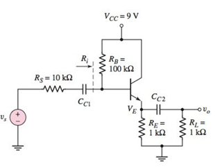
Figure P6.52
A.
The range in the dc values of
Answer to Problem 6.52P
Range of emitter current
and range of emitter current
Explanation of Solution
Given:
Range of transistor current gain
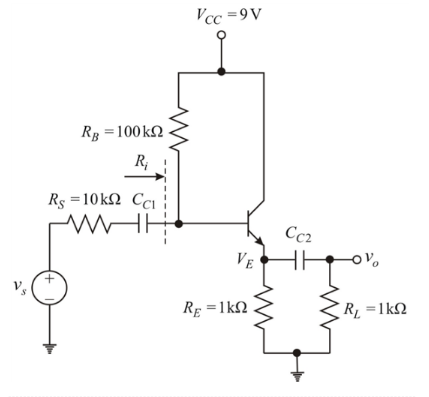
The circuit is given below:

From above circuit, considering BJT s single node, then by KCL, Quiescent emitter current
In CE mode,
From equation (1) and (2),
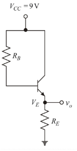
Now, DC analysis of the given circuit:
Reduce source Vs to zero and open the capacitor as shown below:
For
Applying KCL in the base-emitter loop to determine
From equation (3)
Using equation (5) give,
From dc analysis of the circuit, the emitter voltage is,
For
From equation (4)
From equation (3)
Using equation (6) give,
From dc analysis of the circuit, the emitter voltage is,
So, final range of emitter current
and final range of emitter current
B.
Range in the values of input resistance
Answer to Problem 6.52P
Final range of input resistance
and final range of input resistance
Explanation of Solution
Given:
Range of transistor current gain
The circuit is given below:
For
From equation (2)
Now, small signal analysis of the given circuit:
Reduce dc voltage sources to zero, dc current source to open and capacitors to short.
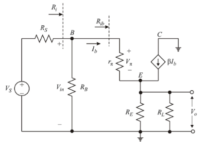
Diffusion resistance
Input resistance
Input resistance
For
From equation (2)
Diffusion resistance
Input resistance
Input resistance
So, final range of input resistance
For
Small signal voltage gain
For
Small signal voltage gain
So, final range of input resistance
Want to see more full solutions like this?
Chapter 6 Solutions
Microelectronics: Circuit Analysis and Design


- A three-phase 20 kV medium-voltage line is 10 km. Resistance is 0.252 2/km and reactance is 0.128 92/km (inductive). Voltage at the beginning of line is 21.0 kV. At the end of the line is loading P = 2.5 MW with power factor 0.92ind. Draw 1-phase equivalent diagram and calculate line voltage at the end the of line, active and reactive power at the beginning of the line and power losses of the line.arrow_forwardA three-phase 20 kV medium-voltage line is 10 km. Resistance is 0.365 2/km and reactance is 0.363 2/km (inductive). Voltage at the beginning of line is 20.5 kV. At the end of the line is loading P= 800 kW with power factor 0.95ind. Draw 1-phase equivalent diagram and calculate load current, line voltage at the end the of line, voltage drop and power losses of the line.arrow_forward6. Answer the following questions. Take help from ChatGPT to answer these questions (if you need). Write the answers briefly using your own words with no more than two sentences, and make sure you check whether ChatGPT is giving you the appropriate answers in our context. A) What is a model in our context? B) What is an LTI system? C) What are the three forms of model we have used in the class so far to represent an LTI system? Among the above three forms, which forms can still be used to represent a nonlinear system?arrow_forward
- 5. Consider the following block diagram of a system in the Figure 4. Y₁(s) G₁ G2. R(s) C(s) Y₂(s) G3 G4 Figure 4 The models of the blocks G1, G2, G3 and G4 are represented by a differential equation, transfer function, state-space form, and impulse response as the followings. dy1 G₁: +2y₁ = 3r(t) dt 1 G2: G₂(s) = S+3 G3: x=2x+r, y2=3x-r G4: h(t)=8(t) + et 1(t) Find the simplified expression of the overall transfer function of the system i.e., G(s) = Note for G3 block, you may need to use the formula H(s) = C (sI - A)-¹ B+ D. C(s) R(s)arrow_forward4. Simplify the block diagram in Figure 3 and find the closed-loop transfer function G(s) = C(s) R(s) G₁ R(s) Figure 3 C(s) G2 H₁ H₂arrow_forward1. Consider a system defined by the following state-space equations. -5 2 N-MAN-G = 3 -1 y = [12] Find the transfer function H(s) = x1 x2. Y(s) U(s)' + 5arrow_forward
- 3. Simplify the block diagram in Figure 2 and find the closed-loop transfer function G(s) = C(s) R(s)' G₁ C(s) R(s) G2 G3 G4 Figure 2arrow_forwardRigid network supplies Feeder 1 through 110/21 kV transformer (Figure 1). Short circuit power of the supplying network is 5000 MVA and voltage is 110 kV. Determine 3-phase short circuit current for the point A. Draw 1-phase equivalent diagram. How big is the current if the 3-phase short circuit occurs in the Busbar? 110/21 kV Busbar Supplying network S = 16MVA 4-10% Figure 1. Feeder 1: 1-5km - r = 0.337 2/km x 0.361 2/km Aarrow_forwardRigid network supplies Feeder 1 through 110/21 kV transformer (Figure 1). Short circuit power of the supplying network is 3000 MVA and voltage is 110 kV. Length of feeder 1 is 5 km. Determine 3-phase short circuit current for the point A. Draw 1-phase equivalent diagram. 110/21 kV Busbar Supplying network S = 16MVA 4-10% Feeder 1: Figure 1. - 1 = 5km r = 0.337 2/km x = 0.361 2/km Aarrow_forward
 Introductory Circuit Analysis (13th Edition)Electrical EngineeringISBN:9780133923605Author:Robert L. BoylestadPublisher:PEARSON
 Delmar's Standard Textbook Of ElectricityElectrical EngineeringISBN:9781337900348Author:Stephen L. HermanPublisher:Cengage Learning
 Programmable Logic ControllersElectrical EngineeringISBN:9780073373843Author:Frank D. PetruzellaPublisher:McGraw-Hill Education
 Fundamentals of Electric CircuitsElectrical EngineeringISBN:9780078028229Author:Charles K Alexander, Matthew SadikuPublisher:McGraw-Hill Education
 Electric Circuits. (11th Edition)Electrical EngineeringISBN:9780134746968Author:James W. Nilsson, Susan RiedelPublisher:PEARSON
 Engineering ElectromagneticsElectrical EngineeringISBN:9780078028151Author:Hayt, William H. (william Hart), Jr, BUCK, John A.Publisher:Mcgraw-hill Education,