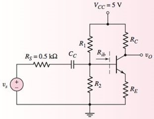
For the circuit in Figure 6.31, let R E = 0.6 kΩ , R C = 5.6 kΩ , β = 120 , V B E (on) = 0.7 V , R 1 = 250 kΩ , and R 2 = 75 kΩ . (a) For V A = ∞ , determine the small−signal voltage gain A υ . (b) Determine the input resistance looking into the base of the transistor. (Ans. (a) A υ = − 8.27 , (b) R i b = 80.1 kΩ ) Figure 6.31 Figure for Exercise Ex6.5
For the circuit in Figure 6.31, let R E = 0.6 kΩ , R C = 5.6 kΩ , β = 120 , V B E (on) = 0.7 V , R 1 = 250 kΩ , and R 2 = 75 kΩ . (a) For V A = ∞ , determine the small−signal voltage gain A υ . (b) Determine the input resistance looking into the base of the transistor. (Ans. (a) A υ = − 8.27 , (b) R i b = 80.1 kΩ ) Figure 6.31 Figure for Exercise Ex6.5
Solution Summary: The circuit for npn common emitter is shown in Figure 1. The transistors parameters are written below.
For the circuit in Figure 6.31, let
R
E
=
0.6
kΩ
,
R
C
=
5.6
kΩ
,
β
=
120
,
V
B
E
(on)
=
0.7
V
,
R
1
=
250
kΩ
, and
R
2
=
75
kΩ
. (a) For
V
A
=
∞
, determine the small−signal voltage gain
A
υ
. (b) Determine the input resistance looking into the base of the transistor. (Ans. (a)
A
υ
=
−
8.27
, (b)
R
i
b
=
80.1
kΩ
)
Can you rewrite the solution because it is
unclear?
AM
(+) = 8(1+0.5 cos 1000kt +0.5 ros 2000 thts)
=
cos 10000 πt.
8 cos wat + 4 cos wit + 4 cos Wat coswet.
J4000 t
j11000rt
$14+) = 45
jqooort
+4e
+ e
+ e
j 12000rt.
12000 kt
+ e
+e
+e
Le
jsoort
-; goon t
te
+e
Dcw>
= 885(W- 100007) + 8 IS (W-10000) -
USB
Can you rewrite the solution because it is
unclear?
Q2
AM
①(+) = 8 (1+0.5 cos 1000πt +0.5 ros 2000kt)
$4+) = 45
=
*cos 10000 πt.
8 cos wat + 4 cosat + 4 cos Wat coswet.
j1000016
+4e
-j10000πt j11000Rt
j gooort -j 9000 πt
+
e
+e
j sooort
te
+e
J11000 t
+ e
te
j 12000rt.
-J12000 kt
+ с
= 8th S(W- 100007) + 8 IS (W-10000)
<&(w) =
USB
-5-5
-4-5-4
b) Pc 2² = 64
PSB =
42
+ 4
2
Pt Pc+ PSB =
y = Pe
c) Puss =
PLSB =
= 32
4² = 8 w
32+ 8 =
× 100% = 140
(1)³×2×2
31
= 20%
x 2 = 3w
302
USB
4.5 5 5.6 6
ms Ac = 4 mi
= 0.5
mz Ac = 4
५
M2
=
=0.5
A. Draw the waveform for the following binary sequence using Bipolar RZ, Bipolar NRZ, and
Manchester code.
Data sequence= (00110100)
B. In a binary PCM system, the output signal-to-quantization ratio is to be hold to a minimum of
50 dB. If the message is a single tone with fm-5 kHz. Determine:
1) The number of required levels, and the corresponding output signal-to-quantizing noise ratio.
2) Minimum required system bandwidth.
Need a deep-dive on the concept behind this application? Look no further. Learn more about this topic, electrical-engineering and related others by exploring similar questions and additional content below.


 Introductory Circuit Analysis (13th Edition)Electrical EngineeringISBN:9780133923605Author:Robert L. BoylestadPublisher:PEARSON
 Delmar's Standard Textbook Of ElectricityElectrical EngineeringISBN:9781337900348Author:Stephen L. HermanPublisher:Cengage Learning
 Programmable Logic ControllersElectrical EngineeringISBN:9780073373843Author:Frank D. PetruzellaPublisher:McGraw-Hill Education
 Fundamentals of Electric CircuitsElectrical EngineeringISBN:9780078028229Author:Charles K Alexander, Matthew SadikuPublisher:McGraw-Hill Education
 Electric Circuits. (11th Edition)Electrical EngineeringISBN:9780134746968Author:James W. Nilsson, Susan RiedelPublisher:PEARSON
 Engineering ElectromagneticsElectrical EngineeringISBN:9780078028151Author:Hayt, William H. (william Hart), Jr, BUCK, John A.Publisher:Mcgraw-hill Education,