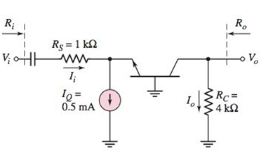
Consider the ac equivalent common−base circuit shown in Figure P6.61. The transistor has parameters β = 110 and V A = ∞ . Determine (a) the voltage gain A υ = V o / V i , (b) the current gain A i = I o / I i , (c) the input resistance R i , and (d) the output resistance R o . Figure P6.61
Consider the ac equivalent common−base circuit shown in Figure P6.61. The transistor has parameters β = 110 and V A = ∞ . Determine (a) the voltage gain A υ = V o / V i , (b) the current gain A i = I o / I i , (c) the input resistance R i , and (d) the output resistance R o . Figure P6.61
Solution Summary: The value of the small signal value voltage gain is given by the expression as shown below.
Consider the ac equivalent common−base circuit shown in Figure P6.61. The transistor has parameters
β
=
110
and
V
A
=
∞
. Determine (a) the voltage gain
A
υ
=
V
o
/
V
i
, (b) the current gain
A
i
=
I
o
/
I
i
, (c) the input resistance
R
i
, and (d) the output resistance
R
o
.
An electric resistance space heater is designed such that it resembles a rectangular box 55 cm high, 75 cm long, and 20
cm wide filled with 45 kg of oil. The heater is to be placed against a wall, and thus heat transfer from its back surface is
negligible. The surface temperature of the heater is not to exceed 75°C in a room at 25°C for safety considerations.
The emissivity of the outer surface of the heater is 0.8 and the average temperature of the ceiling and wall surfaces is the
same as the room air temperature.
The properties of air at 1 atm and the film temperature are: k = 0.02753 W/m-°C, v=1.798 x 10⁻⁵ m²/s, Pr = 0.7228, and ẞ=
0.003096K-1
Wall
T₁ =75°C
Oil
€ = 0.8
Electric heater
Heating element
Disregarding heat transfer from the bottom and top surfaces of the heater in anticipation that the top surface will be used as a shelf,
determine the power rating of the heater in W.
The power rating of the heater is
W.
circuit 2
Suppose you have 8 LED's connected to port-B (Bo-B7) of PIC16F877A and one switch
connected to port-D (Do) as shown in figure below. Write a program code that performs a
nibble (4-bits) toggling: if the switch is released then LED's (Bo to B3) are OFF and LED's
(B4 to B7) are ON, while if the switch is pressed then LED's (Bo to B3) are ON and LED's
(B4 to B7) are OFF. Use 300ms delay for each case with 4MHz frequency.
13
14
22 NATHON 20
U1
OSC1/CLKIN
U2
33
REOINT
20
34
OSC2/CLKOUT
19
RB1
35
3
18
RB2
RADIANO debt0RB3PGM
30
4
17
37
5
10
RA1/AN1
RB4
38
RA2/ANZ/VREF-/CVREF
15
RB5
39097
RA3/AN3VREF RB6/PGC
7
14
40
RA4/TOCK/C1OUT
13
RB7/PGO
RAS/ANA/SS/CZOUT
15
RCO/T1OSO/TICKI
10
11
REQIANS/RD
18
RC1/T10S/CCP2
17
10
RE1/AN/WR
REZ/ANTICS
MCLR/Vpp/THV
RC2/CCP1
LED-BARGRAPH-RED
RC3/SCK/SCL
RC4/SDUSDA
RC5/SDO
Eng of ROSTX/CX
RC7/RX/DT
RDO/PSPO
RD1/PSP1
RD2PSP2
RO3/PSP3
RD4/PSP4
ROS/PSP5
RD6/PSP6
RD7/PSP7
PIC16F877A
+5V
R1
100R
Need a deep-dive on the concept behind this application? Look no further. Learn more about this topic, electrical-engineering and related others by exploring similar questions and additional content below.


 Introductory Circuit Analysis (13th Edition)Electrical EngineeringISBN:9780133923605Author:Robert L. BoylestadPublisher:PEARSON
 Delmar's Standard Textbook Of ElectricityElectrical EngineeringISBN:9781337900348Author:Stephen L. HermanPublisher:Cengage Learning
 Programmable Logic ControllersElectrical EngineeringISBN:9780073373843Author:Frank D. PetruzellaPublisher:McGraw-Hill Education
 Fundamentals of Electric CircuitsElectrical EngineeringISBN:9780078028229Author:Charles K Alexander, Matthew SadikuPublisher:McGraw-Hill Education
 Electric Circuits. (11th Edition)Electrical EngineeringISBN:9780134746968Author:James W. Nilsson, Susan RiedelPublisher:PEARSON
 Engineering ElectromagneticsElectrical EngineeringISBN:9780078028151Author:Hayt, William H. (william Hart), Jr, BUCK, John A.Publisher:Mcgraw-hill Education,