
Microelectronics: Circuit Analysis and Design
4th Edition
ISBN: 9780073380643
Author: Donald A. Neamen
Publisher: McGraw-Hill Companies, The
expand_more
expand_more
format_list_bulleted
Concept explainers
Videos
Textbook Question
Chapter 6, Problem 6.8P
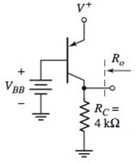
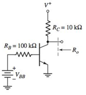
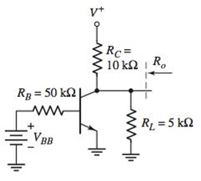
The parameters of each transistor in the circuits shown in Figure P6.8 are
Expert Solution & Answer
Want to see the full answer?
Check out a sample textbook solution
Students have asked these similar questions
2. Suppose
G₁(s) = (s+2)
G₂(s) = (s-3)
C(s)
Find the transfer function G(s):
for each of the following three configurations
R(s)
shown in Figure 1. Note (a) is a cascaded (series) system, (b) is a parallel system, and
(c) is a feedback (closed-loop) system.
€
(c)
C(s)
R(s)
G₁(s)
G2(5)
G₁(s)
R(s)
C(s)
G2(s)
C(s)
R(s)
G₁(s)
G₂(s)
Figure 1
Determine the transformer's active power losses and primary voltage (Figure 1). The
busbar's voltage at the transformer's secondary side is 20.5 kV. Load P is 6 MW, and the
power factor is 0.95ind.
Select a short-circuit withstanding (1-second short circuit length) cable for Feeder 1 in
Figure 1. Values for cables are given in Table 1. The voltage of the supplying network is
now 115 kV and the short-circuit power of the supplying network is 2000 MVA.
Table 1. Technical information of 3-phase cables (10 kV and 20 kV)
Product's name
EA-number
Structural information
20KV
20KV
20 KV
0624250
0624252
0624253
0624254
AHKAMK-W AHKAMKW AHKAMKWAHKAMKW AHKAMKW AHKAMKW AHKAMKW
3x50Al+35Cu 3x95 Al. 35Cu 3x120Al. 35Cu 3x150Al+35Cu 3x185Al+35Cu 3x240A1+70 Cu 3x300Al+70Cu
20kV
20kV 20 kV (8) 20KV
0624255
0624257
0624256
Diameter of conductor
Diameter of out-most circle
Cable's outer diameter
Mass
Delivery information
Standard length
Delivery reel
mm
8.0
11.3
12.7
14.1
15.7
18.1
20.3
mm
28
32
34
35
37
40
43
mm
64
71
74
76
80
89
94
aluminium
kg/km
510
910
1100
1350
1650
2200
2700
сорраг
kg/km
305
305
305
305
305
600
600
cable
kg/km
2350
3100
3450
3800
4300
5500
6250
E
500
500
500
500
500
500
500…
Chapter 6 Solutions
Microelectronics: Circuit Analysis and Design
Ch. 6 - The circuit parameters for the circuit in Figure...Ch. 6 - For the circuit in Figure 6.3, assume transistor...Ch. 6 - For the circuit in Figure 6.14(a), let =90 ,...Ch. 6 - Using the circuit and transistor parameters given...Ch. 6 - Consider the circuit in Figure 6.18. The circuit...Ch. 6 - Repeat Example 6.4 if the quiescent collector...Ch. 6 - For the circuit in Figure 6.31, let RE=0.6k ,...Ch. 6 - Prob. 6.6EPCh. 6 - The parameters of the circuit shown in Figure 6.28...Ch. 6 - For the circuit shown in Figure 6.31, let =100 ,...
Ch. 6 - Design the circuit in Figure 6.35 such that it is...Ch. 6 - For the circuit in Figure 6.28, the smallsignal...Ch. 6 - The circuit in Figure 6.38 has parameters V+=5V ,...Ch. 6 - For the circuit in Figure 6.39, let =125 ,...Ch. 6 - (a) Assume the circuit shown in Figure 6.40(a) is...Ch. 6 - For the circuit in Figure 6.39, let =125 ,...Ch. 6 - Reconsider the circuit in Figure 6.38. Let =120 ,...Ch. 6 - For the circuit shown in Figure 6.48, let =120 ,...Ch. 6 - For the circuit in Figure 6.31, use the parameters...Ch. 6 - Consider the circuit in Figure 6.38. Assume...Ch. 6 - For the circuit shown in Figure 6.49, let VCC=12V...Ch. 6 - Consider the circuit and transistor parameters...Ch. 6 - For the circuit in Figure 6.54, the transistor...Ch. 6 - Assume the circuit in Figure 6.57 uses a 2N2222...Ch. 6 - For the circuit in Figure 6.58, RE=2k , R1=R2=50k...Ch. 6 - Prob. 6.12TYUCh. 6 - For the circuit shown in Figure 6.63, the...Ch. 6 - Prob. 6.14TYUCh. 6 - For the circuit shown in Figure 6.64, let RS=0 ,...Ch. 6 - Consider the circuit in Figure 6.70(a). Let =100 ,...Ch. 6 - In the circuit in Figure 6.74 the transistor...Ch. 6 - Discuss, using the concept of a load line, how a...Ch. 6 - Prob. 2RQCh. 6 - Prob. 3RQCh. 6 - Sketch the hybrid- equivalent circuit of an npn...Ch. 6 - Prob. 5RQCh. 6 - Prob. 6RQCh. 6 - Prob. 7RQCh. 6 - Prob. 8RQCh. 6 - Prob. 9RQCh. 6 - Sketch a simple emitter-follower amplifier circuit...Ch. 6 - Sketch a simple common-base amplifier circuit and...Ch. 6 - Compare the ac circuit characteristics of the...Ch. 6 - Prob. 13RQCh. 6 - Prob. 14RQCh. 6 - (a) Determine the smallsignal parameters gm,r ,...Ch. 6 - (a) The transistor parameters are =125 and VA=200V...Ch. 6 - A transistor has a current gain in the range 90180...Ch. 6 - The transistor in Figure 6.3 has parameters =120...Ch. 6 - Prob. 6.5PCh. 6 - For the circuit in Figure 6.3, =120 , VCC=5V ,...Ch. 6 - The parameters of each transistor in the circuits...Ch. 6 - The parameters of each transistor in the circuits...Ch. 6 - The circuit in Figure 6.3 is biased at VCC=10V and...Ch. 6 - For the circuit in Figure 6.14, =100 , VA= ,...Ch. 6 - Prob. 6.11PCh. 6 - The parameters of the transistor in the circuit in...Ch. 6 - Assume that =100 , VA= , R1=33k , and R2=50k for...Ch. 6 - The transistor parameters for the circuit in...Ch. 6 - For the circuit in Figure P6.15, the transistor...Ch. 6 - Prob. D6.16PCh. 6 - The signal source in Figure P6.18 is s=5sintmV ....Ch. 6 - Consider the circuit shown in Figure P6.19 where...Ch. 6 - Prob. 6.20PCh. 6 - Figure P6.21 The parameters of the transistor in...Ch. 6 - Prob. 6.22PCh. 6 - For the circuit in Figure P6.23, the transistor...Ch. 6 - The transistor in the circuit in Figure P6.24 has...Ch. 6 - For the transistor in the circuit in Figure P6.26,...Ch. 6 - If the collector of a transistor is connected to...Ch. 6 - Consider the circuit shown in Figure P6.13. Assume...Ch. 6 - For the circuit in Figure P6.15, let =100 , VA= ,...Ch. 6 - Consider the circuit in Figure P6.19. The...Ch. 6 - The parameters of the circuit shown in Figure...Ch. 6 - Consider the circuit in Figure P6.26 with...Ch. 6 - For the circuit in Figure P6.20, the transistor...Ch. 6 - In the circuit in Figure P6.22 with transistor...Ch. 6 - For the circuit in Figure P6.24, the transistor...Ch. 6 - Prob. 6.40PCh. 6 - Consider the ac equivalent circuit in Figure...Ch. 6 - For the ac equivalent circuit in Figure P6.42,...Ch. 6 - The circuit and transistor parameters for the ac...Ch. 6 - Consider the circuit in Figure P6.45. The...Ch. 6 - For the transistor in Figure P6.47, =80 and...Ch. 6 - Consider the emitterfollower amplifier shown in...Ch. 6 - The transistor parameters for the circuit in...Ch. 6 - In the circuit shown in Figure P6.51, determine...Ch. 6 - The transistor current gain in the circuit shown...Ch. 6 - Consider the circuit shown in Figure P6.47. The...Ch. 6 - For the circuit in Figure P6.54, the parameters...Ch. 6 - Figure P6.59 is an ac equivalent circuit of a...Ch. 6 - The transistor in the ac equivalent circuit shown...Ch. 6 - Consider the ac equivalent commonbase circuit...Ch. 6 - Prob. 6.62PCh. 6 - The transistor in the circuit shown in Figure...Ch. 6 - Repeat Problem 6.63 with a 100 resistor in series...Ch. 6 - Consider the commonbase circuit in Figure P6.65....Ch. 6 - For the circuit shown in Figure P6.66, the...Ch. 6 - The parameters of the circuit in Figure P6.67 are...Ch. 6 - For the commonbase circuit shown in Figure P6.67,...Ch. 6 - Consider the circuit shown in Figure P6.69. The...Ch. 6 - In the circuit of Figure P6.71, let VEE=VCC=5V ,...Ch. 6 - Consider the ac equivalent circuit in Figure...Ch. 6 - The transistor parameters in the ac equivalent...Ch. 6 - Consider the circuit shown in Figure 6.38. The...Ch. 6 - For the circuit shown in Figure 6.57, the...
Knowledge Booster


Learn more about
Need a deep-dive on the concept behind this application? Look no further. Learn more about this topic, electrical-engineering and related others by exploring similar questions and additional content below.Similar questions
- A three-phase 20 kV medium-voltage line is 10 km. Resistance is 0.252 2/km and reactance is 0.128 92/km (inductive). Voltage at the beginning of line is 21.0 kV. At the end of the line is loading P = 2.5 MW with power factor 0.92ind. Draw 1-phase equivalent diagram and calculate line voltage at the end the of line, active and reactive power at the beginning of the line and power losses of the line.arrow_forwardA three-phase 20 kV medium-voltage line is 10 km. Resistance is 0.365 2/km and reactance is 0.363 2/km (inductive). Voltage at the beginning of line is 20.5 kV. At the end of the line is loading P= 800 kW with power factor 0.95ind. Draw 1-phase equivalent diagram and calculate load current, line voltage at the end the of line, voltage drop and power losses of the line.arrow_forward6. Answer the following questions. Take help from ChatGPT to answer these questions (if you need). Write the answers briefly using your own words with no more than two sentences, and make sure you check whether ChatGPT is giving you the appropriate answers in our context. A) What is a model in our context? B) What is an LTI system? C) What are the three forms of model we have used in the class so far to represent an LTI system? Among the above three forms, which forms can still be used to represent a nonlinear system?arrow_forward
- 5. Consider the following block diagram of a system in the Figure 4. Y₁(s) G₁ G2. R(s) C(s) Y₂(s) G3 G4 Figure 4 The models of the blocks G1, G2, G3 and G4 are represented by a differential equation, transfer function, state-space form, and impulse response as the followings. dy1 G₁: +2y₁ = 3r(t) dt 1 G2: G₂(s) = S+3 G3: x=2x+r, y2=3x-r G4: h(t)=8(t) + et 1(t) Find the simplified expression of the overall transfer function of the system i.e., G(s) = Note for G3 block, you may need to use the formula H(s) = C (sI - A)-¹ B+ D. C(s) R(s)arrow_forward4. Simplify the block diagram in Figure 3 and find the closed-loop transfer function G(s) = C(s) R(s) G₁ R(s) Figure 3 C(s) G2 H₁ H₂arrow_forward1. Consider a system defined by the following state-space equations. -5 2 N-MAN-G = 3 -1 y = [12] Find the transfer function H(s) = x1 x2. Y(s) U(s)' + 5arrow_forward
- 3. Simplify the block diagram in Figure 2 and find the closed-loop transfer function G(s) = C(s) R(s)' G₁ C(s) R(s) G2 G3 G4 Figure 2arrow_forwardRigid network supplies Feeder 1 through 110/21 kV transformer (Figure 1). Short circuit power of the supplying network is 5000 MVA and voltage is 110 kV. Determine 3-phase short circuit current for the point A. Draw 1-phase equivalent diagram. How big is the current if the 3-phase short circuit occurs in the Busbar? 110/21 kV Busbar Supplying network S = 16MVA 4-10% Figure 1. Feeder 1: 1-5km - r = 0.337 2/km x 0.361 2/km Aarrow_forwardRigid network supplies Feeder 1 through 110/21 kV transformer (Figure 1). Short circuit power of the supplying network is 3000 MVA and voltage is 110 kV. Length of feeder 1 is 5 km. Determine 3-phase short circuit current for the point A. Draw 1-phase equivalent diagram. 110/21 kV Busbar Supplying network S = 16MVA 4-10% Feeder 1: Figure 1. - 1 = 5km r = 0.337 2/km x = 0.361 2/km Aarrow_forward
arrow_back_ios
SEE MORE QUESTIONS
arrow_forward_ios
Recommended textbooks for you
 Introductory Circuit Analysis (13th Edition)Electrical EngineeringISBN:9780133923605Author:Robert L. BoylestadPublisher:PEARSON
 Delmar's Standard Textbook Of ElectricityElectrical EngineeringISBN:9781337900348Author:Stephen L. HermanPublisher:Cengage Learning
 Programmable Logic ControllersElectrical EngineeringISBN:9780073373843Author:Frank D. PetruzellaPublisher:McGraw-Hill Education
 Fundamentals of Electric CircuitsElectrical EngineeringISBN:9780078028229Author:Charles K Alexander, Matthew SadikuPublisher:McGraw-Hill Education
 Electric Circuits. (11th Edition)Electrical EngineeringISBN:9780134746968Author:James W. Nilsson, Susan RiedelPublisher:PEARSON
 Engineering ElectromagneticsElectrical EngineeringISBN:9780078028151Author:Hayt, William H. (william Hart), Jr, BUCK, John A.Publisher:Mcgraw-hill Education,
Introductory Circuit Analysis (13th Edition)
Electrical Engineering
ISBN:9780133923605
Author:Robert L. Boylestad
Publisher:PEARSON
Delmar's Standard Textbook Of Electricity
Electrical Engineering
ISBN:9781337900348
Author:Stephen L. Herman
Publisher:Cengage Learning
Programmable Logic Controllers
Electrical Engineering
ISBN:9780073373843
Author:Frank D. Petruzella
Publisher:McGraw-Hill Education
Fundamentals of Electric Circuits
Electrical Engineering
ISBN:9780078028229
Author:Charles K Alexander, Matthew Sadiku
Publisher:McGraw-Hill Education
Electric Circuits. (11th Edition)
Electrical Engineering
ISBN:9780134746968
Author:James W. Nilsson, Susan Riedel
Publisher:PEARSON
Engineering Electromagnetics
Electrical Engineering
ISBN:9780078028151
Author:Hayt, William H. (william Hart), Jr, BUCK, John A.
Publisher:Mcgraw-hill Education,
How does an Antenna work? | ICT #4; Author: Lesics;https://www.youtube.com/watch?v=ZaXm6wau-jc;License: Standard Youtube License