
Concept explainers
Videos
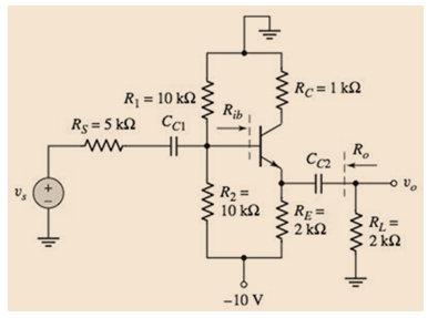
Consider the circuit in Figure P6.45. The transistor parameters are
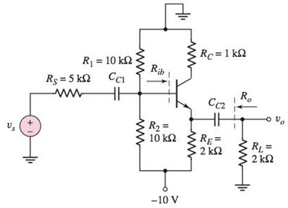
Figure P6.45
a.
The value of the ICQ and VCEQ .
Answer to Problem 6.45P
Explanation of Solution
Given:
The circuit is given as:
Calculation:
Let the BJT be the single node, then by applying Kirchhoff’s current law, the quiescent emitter current
In Common-Emitter mode:
The relation between the quiescent collector current is
For dc analysis,
All the capacitors act as an open circuit and all the ac sources act as short circuits.
DC analysis:
Redrawing the circuit by open circuit, the capacitors, and short circuit the ac sources.
Evaluating the Thevenin resistance
Evaluating the Thevenin voltage,
Drawing the modified circuit:
Applying the Kirchhoff s voltage law in the base-emitter loop,
Substituting
From equation (2):
Substituting
Therefore, the value of
From equation (1) and (2):
Substituting
Substitute
Drawing the modified circuit:
Applying Kirchhoff s voltage law to the loop,
Substituting
Therefore, the value of
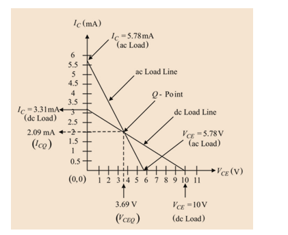
b.
To plot: The dc and the ac load lines.
Explanation of Solution
Given:
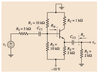
The circuit is given as:
Calculation:
Applying Kirchhoff s voltage law around the collector-emitter loop in figure 1.
Substitute
Substitute
The required “Q” point co-ordinates are
Draw the DC load line:
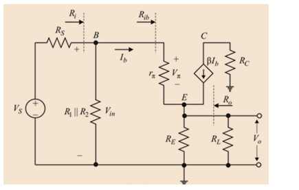
Drawing the AC equivalent circuit:
Evaluating the ac load
The expression for the ac load line:
Substitute
Substitute
Drawing the ac load line:
c.
The small signal voltage gain.
Answer to Problem 6.45P
The small signal voltage gain.
Explanation of Solution
Given:
The circuit is given as:
Drawing the small signal analysis of the circuit by short circuiting the dual dc sources and the capacitors:
Evaluating the diffusion resistance,
Evaluating the small signal transistor output resistance
Evaluating the input resistance
Calculate the input resistance
The small-signal voltage gain is,
d.
The output resistance.
Answer to Problem 6.45P
The output resistance is
Explanation of Solution
Given:
The circuit is given as
Calculation:
From equation 5,
Thus, the input resistance
Calculate the output resistance,
Therefore, the output resistance
Want to see more full solutions like this?
Chapter 6 Solutions
Microelectronics: Circuit Analysis and Design


- a) In terms of n and p, how many state variables and how many inputs can you see in the system below? dx1 = 4x1 = x2 dt dx2 =-3x12x2 +U1 dt b) Derive the state space representation for the above system c) Determine whether the system is stable or not.arrow_forwardmatch each statement to the proper circuit. All circuits have been drawn with a light (L) to represent the load, whether it is a motor, bell, light or any other load. In addition, each switch is illustrated as a push button whether it is maintained switch, momentary contact switch, pushbutton, switch-on target, or any other type of switch.arrow_forwarda) In terms of n and p, how many state variables and how many inputs can you see in the system below? dx1 =-7x1 + x2 + 5u1 dt dx2 =-11x1+x3 + 2u1 dt dx3 = -8x16u1 dt b) Derive the state space representation for the above system c) Determine whether the system is stable or not.arrow_forward
- Question 2 (20 points) a) In terms of n and p, how many state variables and how many inputs can you see in the system below? dx1 dt =x1- 2x2 dx2 = 3x1 - 4x2 dt b) Derive the state space representation for the above system c) Determine whether the system is stable or not.arrow_forwardStuck on the question. Please do not use AI, it will get the answer wrong.arrow_forwardConsider a particle confined in an infinite potential well as shown below and its wave function Solve the following problems. is derived as √(x) = A sin (TA), and energy E= H U 0 U=0 a x πλη 2ma² €30 (iii) Calculate the value of A. [Hint: The probability of finding the particle in 0arrow_forwardQ2: Using D flip-flops, design a synchronous counter. The counter counts in the sequence 1,3,5,7, 1,7,5,3,1,3,5,7,.... when its enable input x is equal to 1; otherwise, the counter count 0.arrow_forward8.19 In the circuit shown in Fig. P8.19, u(t) = 40cos(105t) V,R1 = 100 W, R2 = 500 W, C = 0.1 μF, and L = 0.5 mH.Determine the complex power for each passive element, and verifythat conservation of energy is satisfied.arrow_forwardIn the circuit shown, let R₁=7, R₂=12, R3=24, R4-2, V₁ =26, V2=104, and V3-78, to calculate the power delivered (or absorbed) by the circuit inside the box, as follows: {NOTE: On Multiple Choice Questions, like this problem, you have only one attempt } 1. The current I is equal to (choose the closed values in amperes) O 1.156 -1.156 -1.209 -4.622 1.209 0 (A) 4.622 2. The power delivered (or absorbed) (choose the closest value in watts) (W) -873.292 152.225 O 873.292 -122.181 -58.086 0 O 122.181 R₁ ww V₂ R₂ R3 V1 ww R4 √3arrow_forwardFor the circuit shown, find the currents 11, 12, 16 and 17, given 13 =1 A, 14-19 A, 15 =-10 A, and Ig =5 A. = (A) 12 = (A) 16 = (A) 175 (A) (Based on Alexander Textbook, Chapter2) I5 12 14 18 13 16 • Round your values to 3-significant digits.arrow_forwardIn the circuit shown, let R₁=62, R2=39, R3=16, R4-7 and V5-194, to calculate Vo and lo, as follows: V₁ R1 R3 Find the overall current i delivered by the voltage source Vs: • Find the voltage Vo: • Find the current l₁ : The relative tolerance for this problem is 7 %. (V) (A) www. R₂ + RA (A)arrow_forwardFor the circuit shown, let V₁ =35 V, V₂-7 V, and R=45 $2, ⚫ The current I = • The power absorbed by the resistor R; PR (A) find: • The power delivered/absorbed by the voltage source V₁; Pv₁= ⚫ The power delivered/absorbed by the voltage source V2; Pv2= ⚫ The power delivered/absorbed by the voltage source (-8V); P-8 = V₁ (1+ √2 + (+ −8 V (W) (W) (W) (W) Rarrow_forwardarrow_back_iosSEE MORE QUESTIONSarrow_forward_ios
 Introductory Circuit Analysis (13th Edition)Electrical EngineeringISBN:9780133923605Author:Robert L. BoylestadPublisher:PEARSON
 Delmar's Standard Textbook Of ElectricityElectrical EngineeringISBN:9781337900348Author:Stephen L. HermanPublisher:Cengage Learning
 Programmable Logic ControllersElectrical EngineeringISBN:9780073373843Author:Frank D. PetruzellaPublisher:McGraw-Hill Education
 Fundamentals of Electric CircuitsElectrical EngineeringISBN:9780078028229Author:Charles K Alexander, Matthew SadikuPublisher:McGraw-Hill Education
 Electric Circuits. (11th Edition)Electrical EngineeringISBN:9780134746968Author:James W. Nilsson, Susan RiedelPublisher:PEARSON
 Engineering ElectromagneticsElectrical EngineeringISBN:9780078028151Author:Hayt, William H. (william Hart), Jr, BUCK, John A.Publisher:Mcgraw-hill Education,