
Machine Elements in Mechanical Design (6th Edition) (What's New in Trades & Technology)
6th Edition
ISBN: 9780134441184
Author: Robert L. Mott, Edward M. Vavrek, Jyhwen Wang
Publisher: PEARSON
expand_more
expand_more
format_list_bulleted
Concept explainers
Videos
Textbook Question
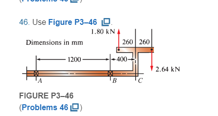
Chapter 3, Problem 46P
For Problems 39 through 50, draw the free-body diagram of only the horizontal beam portion of the given figures. Then draw the complete shear and bending moment diagrams. Where used, the symbol X indicates a simple support capable of exerting a reaction force in any direction but having no moment resistance. For beams having unbalanced axial loads, you may specify which support offers the reaction.
Expert Solution & Answer
Want to see the full answer?
Check out a sample textbook solution
Students have asked these similar questions
M
× Your answer is incorrect.
(Manometer) Determine the angle 0 of the inclined tube shown in figure below if the pressure at A is 1 psi greater than that at B.
1ft
SG=0.61
十
A
Ꮎ
1ft
SG=1.0
8.8 ft
0 =
Hi
15.20
deg
Air
I don't know how to solve this
Chapter 3 Solutions
Machine Elements in Mechanical Design (6th Edition) (What's New in Trades & Technology)
Ch. 3 - A tensile member in a machine structure is...Ch. 3 - Compute the stress in a round bar having a...Ch. 3 - Compute the stress in a rectangular bar having...Ch. 3 - A link in a packaging machine mechanism has a...Ch. 3 - Two circular rods support the 3800 lb weight of a...Ch. 3 - A tensile load of 5.00 kN is applied to a square...Ch. 3 - An aluminum rod is made in the form of a hollow...Ch. 3 - Compute the stress in the middle portion of rod AC...Ch. 3 - Compute the forces in the two angled rods in...Ch. 3 - If the rods from Problem 9 are circular, determine...
Ch. 3 - Repeat Problems 9 and 10 if the angle is 15 .Ch. 3 - Figure P312 shows a small truss spanning between...Ch. 3 - The truss shown in Figure P313 spans a total space...Ch. 3 - Figure P314 shows a short leg for a machine that...Ch. 3 - Consider the short compression member shown in...Ch. 3 - Refer Figure P38 . Each of the pins at A, B, and C...Ch. 3 - Compute the shear stress in the pins connecting...Ch. 3 - Prob. 18PCh. 3 - Prob. 19PCh. 3 - Prob. 20PCh. 3 - Prob. 21PCh. 3 - Compute the torsional shear stress in a circular...Ch. 3 - If the shaft of Problem 22 is 850 mm long and is...Ch. 3 - Compute the torsional shear stress due to a torque...Ch. 3 - Compute the torsional shear stress in a solid...Ch. 3 - Compute the torsional shear stress in a hollow...Ch. 3 - Compute the angle of twist for the hollow shaft of...Ch. 3 - A square steel bar, 25 mm on a side and 650 mm...Ch. 3 - A 3.00 in-diameter steel bar has a flat milled on...Ch. 3 - A commercial steel supplier lists rectangular...Ch. 3 - A beam is simply supported and carries the load...Ch. 3 - For each beam of Problem 31, compute its weight if...Ch. 3 - For each beam of Problem 31, compute the maximum...Ch. 3 - For the beam loading of Figure P334, draw the...Ch. 3 - For the beam loading of Figure P334, design the...Ch. 3 - Figure P336 shows a beam made from 4 in schedule...Ch. 3 - Select an aluminum I-beam shape to carry the load...Ch. 3 - Figure P338 represents a wood joist for a...Ch. 3 - For Problems 39 through 50, draw the free-body...Ch. 3 - Prob. 40PCh. 3 - For Problems 39 through 50, draw the free-body...Ch. 3 - Prob. 42PCh. 3 - Prob. 43PCh. 3 - Prob. 44PCh. 3 - For Problems 39 through 50, draw the free-body...Ch. 3 - For Problems 39 through 50, draw the free-body...Ch. 3 - For Problems 39 through 50, draw the free-body...Ch. 3 - For Problems 4850, draw the free-body diagram of...Ch. 3 - For Problems 4850, draw the free-body diagram of...Ch. 3 - Prob. 50PCh. 3 - Compute the maximum tensile stress in the bracket...Ch. 3 - Compute the maximum tensile and compressive...Ch. 3 - For the lever shown in Figure P353 (a), compute...Ch. 3 - Compute the maximum tensile stress at sections A...Ch. 3 - Prob. 55PCh. 3 - Refer to Figure P38. Compute the maximum tensile...Ch. 3 - Prob. 57PCh. 3 - Refer to P342. Compute the maximum stress in the...Ch. 3 - Refer to P343. Compute the maximum stress in the...Ch. 3 - Prob. 60PCh. 3 - Figure P361 shows a valve stem from an engine...Ch. 3 - The conveyor fixture shown in Figure P362 carries...Ch. 3 - For the flat plate in tension in Figure P363,...Ch. 3 - For Problems 64 through 68, compute the maximum...Ch. 3 - For Problems 64 through 68, compute the maximum...Ch. 3 - For Problems 64 through 68, compute the maximum...Ch. 3 - For Problems 64 through 68, compute the maximum...Ch. 3 - Prob. 68PCh. 3 - Figure P369 shows a horizontal beam supported by a...Ch. 3 - Prob. 70PCh. 3 - Prob. 71PCh. 3 - The beam shown in Figure P372 is a stepped, flat...Ch. 3 - Figure P373 shows a stepped, flat bar having a...Ch. 3 - Figure P374 shows a bracket carrying opposing...Ch. 3 - Prob. 75PCh. 3 - Figure P376 shows a lever made from a rectangular...Ch. 3 - For the lever in P376, determine the maximum...Ch. 3 - Figure P378 shows a shaft that is loaded only in...Ch. 3 - Prob. 79PCh. 3 - Prob. 80PCh. 3 - A hanger is made from ASTM A36 structural steel...Ch. 3 - A coping saw frame shown in Figure P382 is made...Ch. 3 - Prob. 83PCh. 3 - Figure P384 shows a hand garden tool used to break...Ch. 3 - Figure P385 shows a basketball backboard and goal...Ch. 3 - Prob. 86P
Knowledge Booster


Learn more about
Need a deep-dive on the concept behind this application? Look no further. Learn more about this topic, mechanical-engineering and related others by exploring similar questions and additional content below.Similar questions
- 1. The maximum and minimum stresses as well as the shear stress seen subjected the piece in plane A-A. Assume it is a cylinder with a diameter of 12.7mm 2. Draw the Mohr circle for the stress state using software. 3. Selection of the material for the prosthesis, which must be analyzed from the point of safety and cost view.arrow_forwardFirst, define the coordinate system XY with its origin at O2 and X-axis passing through O4 asshown above, then based on the provided steps Perform coordinate transformation from XY to xy to get the trajectory of point P. Show all the steps and calcualtionsarrow_forwardI don't know how to solve thisarrow_forward
- Question 2 (40 Points) Consider the following double pendulum-like system with links ₁ and 12. The angles 0 and & could have angular velocities ėêk and êk, respectively, where ②k is a unit vector that points out of the page and is perpendicular to x and y. They could also have angular accelerations Ök and êk. The angle is defined relative to the angle 0. The link 12 is a spring and can extend or compress at a rate of 12. It can also have a rate of extension or compression Ï2. li y êr1 êe 12 χ 3 еф er2 ده لج 1) Express the velocity of the mass in terms of the unit vectors ê0, êr1, êø, and êr2, and any extension/contraction of the links (e.g.,. i; and Ï¿) (12 Points) 2) Express the acceleration of the mass in terms of the unit vectors ê¤, ê×1, êp, and êÃ2, and any extension/contraction of the links (e.g.,. İ; and Ï¿) (12 Points) 3) Express the velocity of the mass in terms of unit vectors î and ĵ that point in the x and y directions, respectively. Also include the appropriate,…arrow_forwardprovide step by step solutions for angles teta 3 and teta 4 by the vector loopmethod. Show work in: vector loop, vector equations, solution procedure.arrow_forward(Manometer) A tank is constructed of a series of cylinders having diameters of 0.35, 0.30, and 0.20 m as shown in the figure below. The tank contains oil, water, and glycerin and a mercury manometer is attached to the bottom as illustrated. Calculate the manometer reading, h. 0.11 m + SAE 30 Oil 0.13 m + Water 0.10 m Glycerin + 0.10 m Mercury h = marrow_forward
- P = A piston having a cross-sectional area of 0.40 m² is located in a cylinder containing water as shown in the figure below. An open U-tube manometer is connected to the cylinder as shown. For h₁ = 83 mm and h = 111 mm what is the value of the applied force, P, acting on the piston? The weight of the piston is negligible. Hi 5597.97 N P Piston Water Mercuryarrow_forwardStudent Name: Student Id: College of Applied Engineering Al-Muzahmiyah Branch Statics (AGE 1330) Section-1483 Quiz-2 Time: 20 minutes Date: 16/02/2025 Q.1. A swinging door that weighs w=400.0N is supported by hinges A and B so that the door can swing about a vertical' axis passing through the hinges (as shown in below figure). The door has a width of b=1.00m and the door slab has a uniform mass density. The hinges are placed symmetrically at the door's edge in such a way that the door's weight is evenly distributed between them. The hinges are separated by distance a=2.00m. Find the forces on the hinges when the door rests half-open. Draw Free body diagram also. [5 marks] [CLO 1.2] Mool b ర a 2.0 m B 1.0 marrow_forwardFor the walking-beam mechanism shown in Figure 3, find and plot the x and y coordinates of the position of the coupler point P for one complete revolution of the crank O2A. Use the coordinate system shown in Figure 3. Hint: Calculate them first with respect to the ground link 0204 and then transform them into the global XY coordinate system. y -1.75 Ꮎ Ꮎ 4 = 2.33 0242.22 L4 x AP = 3.06 L2 = 1.0 W2 31° B 03 L3 = 2.06 P 1 8 5 .06 6 7 P'arrow_forward
- The link lengths, gear ratio (2), phase angle (Ø), and the value of 02 for some geared five bar linkages are defined in Table 2. The linkage configuration and terminology are shown in Figure 2. For the rows assigned, find all possible solutions for angles 03 and 04 by the vector loop method. Show your work in details: vector loop, vector equations, solution procedure. Table 2 Row Link 1 Link 2 Link 3 Link 4 Link 5 λ Φ Ө a 6 1 7 9 4 2 30° 60° P y 4 YA B b R4 R3 YA A Gear ratio: a 02 d 05 r5 R5 R2 Phase angle: = 0₂-202 R1 05 02 r2 Figure 2. 04 Xarrow_forwardProblem 4 A .025 lb bullet C is fired at end B of the 15-lb slender bar AB. The bar is initially at rest, and the initial velocity of the bullet is 1500 ft/s as shown. Assuming that the bullet becomes embedded in the bar, find (a) the angular velocity @2 of the bar immediately after impact, and (b) the percentage loss of kinetic energy as a result of the impact. (c) After the impact, does the bar swing up 90° and reach the horizontal? If it does, what is its angular velocity at this point? Answers: (a). @2=1.6 rad/s; (b). 99.6% loss = (c). Ah2 0.212 ft. The bar does not reach horizontal. y X 4 ft 15 lb V₁ 1500 ft/s 0.025 lb C 30°7 B Aarrow_forwardsubject: combustion please include complete solution, no rounding off, with diagram/explanation etc. In a joule cycle, intake of the compressor is 40,000 cfm at 0.3 psig and 90 deg F. The compression ratio is 6.0 and the inlet temperature at the turbine portion is 1900R while at the exit, it is 15 psi. Calculate for the back work ratio in percent.arrow_forward
arrow_back_ios
SEE MORE QUESTIONS
arrow_forward_ios
Recommended textbooks for you
 International Edition---engineering Mechanics: St...Mechanical EngineeringISBN:9781305501607Author:Andrew Pytel And Jaan KiusalaasPublisher:CENGAGE L
International Edition---engineering Mechanics: St...
Mechanical Engineering
ISBN:9781305501607
Author:Andrew Pytel And Jaan Kiusalaas
Publisher:CENGAGE L
Understanding Shear Force and Bending Moment Diagrams; Author: The Efficient Engineer;https://www.youtube.com/watch?v=C-FEVzI8oe8;License: Standard YouTube License, CC-BY
Bending Stress; Author: moodlemech;https://www.youtube.com/watch?v=9QIqewkE6xM;License: Standard Youtube License