
Machine Elements in Mechanical Design (6th Edition) (What's New in Trades & Technology)
6th Edition
ISBN: 9780134441184
Author: Robert L. Mott, Edward M. Vavrek, Jyhwen Wang
Publisher: PEARSON
expand_more
expand_more
format_list_bulleted
Videos
Textbook Question
Chapter 3, Problem 8P
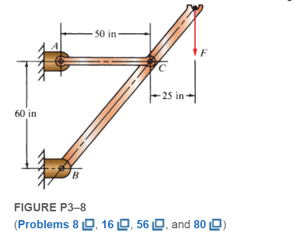
Compute the stress in the middle portion of rod AC in Figure P3−8if the vertical force on the boom is 2500 lb. The rod is rectangular, 1.50 in by 3.50 in.
Expert Solution & Answer
Want to see the full answer?
Check out a sample textbook solution
Students have asked these similar questions
Can you draw the left view of the first orthographic projection
Important:
I've posted this question twice and received incorrect answers. I've clearly stated that I don't require AI-generated working out. I need a genuine, expert-written solution with proper working. If you can't provide that, refer this question to someone who can please!.
Note:
Please provide a clear, step-by-step handwritten solution (no AI involvement). I require an expert-level answer and will assess it based on quality and accuracy with that I'll give it a thumbs up or down!. Hence, refer to the provided image for clarity. Double-check everything for correctness before submitting. Thank you!
Note:
Please provide a clear, step-by-step simplified handwritten working out (no explanations!), ensuring it is done without any AI involvement. I require an expert-level answer, and I will assess and rate based on the quality and accuracy of your work and refer to the provided image for more clarity. Make sure to double-check everything for correctness before submitting appreciate your time and effort!.
Question:
Chapter 3 Solutions
Machine Elements in Mechanical Design (6th Edition) (What's New in Trades & Technology)
Ch. 3 - A tensile member in a machine structure is...Ch. 3 - Compute the stress in a round bar having a...Ch. 3 - Compute the stress in a rectangular bar having...Ch. 3 - A link in a packaging machine mechanism has a...Ch. 3 - Two circular rods support the 3800 lb weight of a...Ch. 3 - A tensile load of 5.00 kN is applied to a square...Ch. 3 - An aluminum rod is made in the form of a hollow...Ch. 3 - Compute the stress in the middle portion of rod AC...Ch. 3 - Compute the forces in the two angled rods in...Ch. 3 - If the rods from Problem 9 are circular, determine...
Ch. 3 - Repeat Problems 9 and 10 if the angle is 15 .Ch. 3 - Figure P312 shows a small truss spanning between...Ch. 3 - The truss shown in Figure P313 spans a total space...Ch. 3 - Figure P314 shows a short leg for a machine that...Ch. 3 - Consider the short compression member shown in...Ch. 3 - Refer Figure P38 . Each of the pins at A, B, and C...Ch. 3 - Compute the shear stress in the pins connecting...Ch. 3 - Prob. 18PCh. 3 - Prob. 19PCh. 3 - Prob. 20PCh. 3 - Prob. 21PCh. 3 - Compute the torsional shear stress in a circular...Ch. 3 - If the shaft of Problem 22 is 850 mm long and is...Ch. 3 - Compute the torsional shear stress due to a torque...Ch. 3 - Compute the torsional shear stress in a solid...Ch. 3 - Compute the torsional shear stress in a hollow...Ch. 3 - Compute the angle of twist for the hollow shaft of...Ch. 3 - A square steel bar, 25 mm on a side and 650 mm...Ch. 3 - A 3.00 in-diameter steel bar has a flat milled on...Ch. 3 - A commercial steel supplier lists rectangular...Ch. 3 - A beam is simply supported and carries the load...Ch. 3 - For each beam of Problem 31, compute its weight if...Ch. 3 - For each beam of Problem 31, compute the maximum...Ch. 3 - For the beam loading of Figure P334, draw the...Ch. 3 - For the beam loading of Figure P334, design the...Ch. 3 - Figure P336 shows a beam made from 4 in schedule...Ch. 3 - Select an aluminum I-beam shape to carry the load...Ch. 3 - Figure P338 represents a wood joist for a...Ch. 3 - For Problems 39 through 50, draw the free-body...Ch. 3 - Prob. 40PCh. 3 - For Problems 39 through 50, draw the free-body...Ch. 3 - Prob. 42PCh. 3 - Prob. 43PCh. 3 - Prob. 44PCh. 3 - For Problems 39 through 50, draw the free-body...Ch. 3 - For Problems 39 through 50, draw the free-body...Ch. 3 - For Problems 39 through 50, draw the free-body...Ch. 3 - For Problems 4850, draw the free-body diagram of...Ch. 3 - For Problems 4850, draw the free-body diagram of...Ch. 3 - Prob. 50PCh. 3 - Compute the maximum tensile stress in the bracket...Ch. 3 - Compute the maximum tensile and compressive...Ch. 3 - For the lever shown in Figure P353 (a), compute...Ch. 3 - Compute the maximum tensile stress at sections A...Ch. 3 - Prob. 55PCh. 3 - Refer to Figure P38. Compute the maximum tensile...Ch. 3 - Prob. 57PCh. 3 - Refer to P342. Compute the maximum stress in the...Ch. 3 - Refer to P343. Compute the maximum stress in the...Ch. 3 - Prob. 60PCh. 3 - Figure P361 shows a valve stem from an engine...Ch. 3 - The conveyor fixture shown in Figure P362 carries...Ch. 3 - For the flat plate in tension in Figure P363,...Ch. 3 - For Problems 64 through 68, compute the maximum...Ch. 3 - For Problems 64 through 68, compute the maximum...Ch. 3 - For Problems 64 through 68, compute the maximum...Ch. 3 - For Problems 64 through 68, compute the maximum...Ch. 3 - Prob. 68PCh. 3 - Figure P369 shows a horizontal beam supported by a...Ch. 3 - Prob. 70PCh. 3 - Prob. 71PCh. 3 - The beam shown in Figure P372 is a stepped, flat...Ch. 3 - Figure P373 shows a stepped, flat bar having a...Ch. 3 - Figure P374 shows a bracket carrying opposing...Ch. 3 - Prob. 75PCh. 3 - Figure P376 shows a lever made from a rectangular...Ch. 3 - For the lever in P376, determine the maximum...Ch. 3 - Figure P378 shows a shaft that is loaded only in...Ch. 3 - Prob. 79PCh. 3 - Prob. 80PCh. 3 - A hanger is made from ASTM A36 structural steel...Ch. 3 - A coping saw frame shown in Figure P382 is made...Ch. 3 - Prob. 83PCh. 3 - Figure P384 shows a hand garden tool used to break...Ch. 3 - Figure P385 shows a basketball backboard and goal...Ch. 3 - Prob. 86P
Knowledge Booster


Learn more about
Need a deep-dive on the concept behind this application? Look no further. Learn more about this topic, mechanical-engineering and related others by exploring similar questions and additional content below.Similar questions
- Note: Please provide a clear, step-by-step simplified handwritten working out (no explanations!), ensuring it is done without any AI involvement. I require an expert-level answer, and I will assess and rate based on the quality and accuracy of your work and refer to the provided image for more clarity. Make sure to double-check everything for correctness before submitting appreciate your time and effort!. Question: If the flow rate through the system below is 0.04m3s-1, find the difference in elevation H of the two reservoirs.arrow_forwardNote: Please provide a clear, step-by-step simplified handwritten working out (no explanations!), ensuring it is done without any AI involvement. I require an expert-level answer, and I will assess and rate based on the quality and accuracy of your work and refer to the provided image for more clarity. Make sure to double-check everything for correctness before submitting thanks!. Question: (In the image as provided)arrow_forwardNote: Please provide a clear, step-by-step simplified handwritten working out (no explanations!), ensuring it is done without any AI involvement. I require an expert-level answer, and I will assess and rate based on the quality and accuracy of your work and refer to the provided image for more clarity. Make sure to double-check everything for correctness before submitting thanks!. Question: The rectangular gate shown below is 3 m wide. Compute the force P needed to hold the gate in the position shown.arrow_forward
- Note: Please provide a clear, step-by-step simplified handwritten working out (no explanations!), ensuring it is done without any AI involvement. I require an expert-level answer, and I will assess and rate based on the quality and accuracy of your work and refer to the provided image for more clarity. Make sure to double-check everything for correctness before submitting thanks!. Question1: If the following container is 0.6m high, 1.2m wide and half full with water, determine the pressure acting at points A, B, and C if ax=2.6ms^-2.arrow_forwardPlease read the imagearrow_forwardChapter 12 - Lecture Notes.pptx: (MAE 272-01) (SP25) DY... Scoresarrow_forwardConsider a large 6-cm-thick stainless steel plate (k = 15.1 W/m-K) in which heat is generated uniformly at a rate of 5 × 10⁵ W/m³. Both sides of the plate are exposed to an environment at 30°C with a heat transfer coefficient of 60 W/m²K. Determine the value of the highest and lowest temperature. The highest temperature is The lowest temperature is °C. °C.arrow_forwardSketch and explain a PV Diagram and a Temperature Entropy Diagram for a 4 stroke diesel engine please, please explain into detail the difference bewteen the two and referance the a diagram. Please include a sketch or an image of each diagramarrow_forwardDraw left view of the first orthographic projectionarrow_forwardSketch and Describe a timing diagram for a 2 stroke diesel engine emphasis on the 2 stroke as my last answer explained 4 stroke please include a diagram or sketch.arrow_forwardA 4 ft 200 Ib 1000 Ib.ft C 2 ft 350 Ib - за в 2.5 ft 150 Ib 250 Ib 375 300 Ib Replace the force system acting on the frame. shown in the figure by a resultant force (magnitude and direction), and specify where its line of action intersects member (AB), measured from point (A).arrow_forwardA continuous flow calorimeter was used to obtain the calorific value of a sample of fuel and the following data collected: Mass of fuel: 2.25 kgInlet water temperature: 11 ° COutlet water temperature 60 ° CQuantity of water: 360 Liters Calorimeter efficiency: 85%Calculate the calorific value of the sample ( kJ / kg ). ive submitted this question twice and have gotten two way different answers. looking for some help thanksarrow_forwardarrow_back_iosSEE MORE QUESTIONSarrow_forward_ios
Recommended textbooks for you
 Mechanics of Materials (MindTap Course List)Mechanical EngineeringISBN:9781337093347Author:Barry J. Goodno, James M. GerePublisher:Cengage Learning
Mechanics of Materials (MindTap Course List)
Mechanical Engineering
ISBN:9781337093347
Author:Barry J. Goodno, James M. Gere
Publisher:Cengage Learning
Mechanical SPRING DESIGN Strategy and Restrictions in Under 15 Minutes!; Author: Less Boring Lectures;https://www.youtube.com/watch?v=dsWQrzfQt3s;License: Standard Youtube License