
Concept explainers
Videos
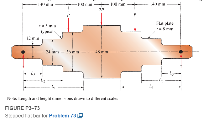
Figure P3−73 shows a stepped, flat bar having a constant thickness of 8.0 mm. It carries three concentrated loads as shown.
Want to see the full answer?
Check out a sample textbook solution
Chapter 3 Solutions
Machine Elements in Mechanical Design (6th Edition) (What's New in Trades & Technology)


- mylabmastering.pearson.com Access Pearson P Pearson MyLab and Mastering P Course Home b My Questions | bartleby Study Area Document Sharing User Settings The 100-kg crate is subjected to the forces shown. The crate is originally at rest. The coefficient of kinetic friction between the crate and the surface is μk = 0.2. (Figure 1) Part A Determine the distance it slides in order to attain a speed of 8.1 m/s. Express your answer to three significant figures and include the appropriate units. Figure 500 N 1 of 1 Α S = Value Units Submit Request Answer Provide Feedback ? ■Review Next >arrow_forwardThe differential equation of a DC motor can be described by the following equation Find the transfer function between the applied voltage ( Va)and the motor speed (thetadot m). What is the steady state speed of the motor after a voltage (Va = 10V) has been applied. Find the transfer function between the applied voltage (Va) and the shaft angle (thetadot m) .arrow_forwardStudy Area Document Sharing User Settings Access Pearson mylabmastering.pearson.com P Pearson MyLab and Mastering The crash cushion for a highway barrier consists of a nest of barrels filled with an impact-absorbing material. The barrier stopping force is measured versus the vehicle penetration into the barrier. (Figure 1) Part A P Course Home b My Questions | bartleby Review Determine the distance a car having a weight of 4000 lb will penetrate the barrier if it is originally traveling at 55 ft/s when it strikes the first barrel. Express your answer to three significant figures and include the appropriate units. Figure 1 of 1 36 μΑ S = Value Units Submit Request Answer Provide Feedback ? Next >arrow_forward
- Study Area Document Sharing User Settings mylabmastering.pearson.com Access Pearson P Pearson MyLab and Mastering Part A P Course Home b My Questions | bartleby ■Review The sports car has a mass of 2.5 Mg and accelerates at 6 m/s², starting from rest. (Figure 1) If the drag resistance on the car due to the wind is FD = (10v) N, where v is the velocity in m/s, determine the power supplied to the engine when t = 5 s. The engine has a running efficiency of € = 0.66. Express your answer to three significant figures and include the appropriate units. Figure 1 of 1 о Α ? P = Value Units Submit Request Answer Return to Assignment Provide Feedbackarrow_forwardAccess Pearson Study Area mylabmastering.pearson.com P Pearson MyLab and Mastering Document Sharing User Settings The car in (Figure 1) having a mass of 2 Mg is originally traveling at 2 m/s. Assume 0 = 22°. Figure 1 of 1 Part A P Course Home b My Questions | bartleby ■Review Determine the distance it must be towed by a force F = 4 kN in order to attain a speed of 6 m/s. Neglect friction and the mass of the wheels. Express your answer to three significant figures and include the appropriate units. Α ? S = Value Units Submit Request Answer Provide Feedback Next >arrow_forwardDerive the Laplace transform of the following functions. Use the definition of Laplace transform. f(t)=sin4t and f(t)=cos2t Auto Controlsarrow_forward
- Study Area Document Sharing User Settings Access Pearson P Pearson MyLab and Mastering Marbles having a mass of 5 g fall from rest at A through the glass tube and accumulate in the can at C. (Figure 1) Figure Aarrow_forwardVC Vc B S TDC -BDC S TQ Tp = Pg A (asne) [1+ % CUSA] At what position (in degrees after top dead center) would you want the peak pressure of combustion to occur to create the maximum torque on the crankshaft? For a 100mm piston digimeter acting on a connecting. rod with a length of 80mm use the equation above to calculate the torque (NIM) on the crankshaft at this crank position for an engine that develops a peak pressure of 135 bararrow_forwardAccess Pearson P Pearson MyLab and Mastering Study Area Document Sharing User Settings The man having a weight of 180 lb is able to run up a 18-ft-high flight of stairs shiwn in (Figure 1) in 4 s. Figure 1 of 1 R mylabmastering.pearson.com Part A P Course Home b My Questions | bartleby Determine the power generated. Express your answer in horsepower to three significant figures. ΜΕ ΑΣΦ. Η vec P = Submit Request Answer Part B ? hp How long would a 100-W light bulb have to burn to expend the same amount of energy? Express your answer to three significant figures and include the appropriate units. HÅ ? t = Value Units Submit Request Answer Provide Feedback Review Next >arrow_forward
- The tension in the belt is 46 lb. Determine the moment of the force F1 about the pin at A. Determine the moment of the force F2 about the pin at A.arrow_forward1. Describe each of the tolerances in the following drawing: 0.01 A 09±0.025 .10±0.01 0.015 AB 6.76 08.51 03±0.05 0.015 MAB 14±0.03 60 14±0.02 12±0.08 0.01 A Barrow_forwardwhat is the intake flow in cfm of a 5.3 liter engine running at 6200 RPM with a volumetric efficiency of 86%. If we supercharge it to flow 610 CFM what is the volumetric efficiency?arrow_forward
 Mechanics of Materials (MindTap Course List)Mechanical EngineeringISBN:9781337093347Author:Barry J. Goodno, James M. GerePublisher:Cengage Learning