
Machine Elements in Mechanical Design (6th Edition) (What's New in Trades & Technology)
6th Edition
ISBN: 9780134441184
Author: Robert L. Mott, Edward M. Vavrek, Jyhwen Wang
Publisher: PEARSON
expand_more
expand_more
format_list_bulleted
Videos
Textbook Question
Chapter 3, Problem 38P
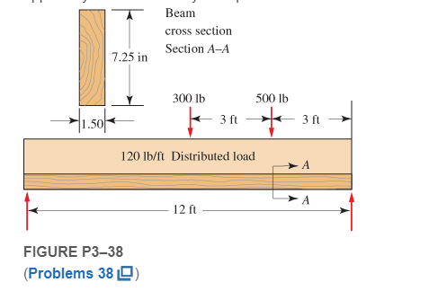
Figure P3−38 represents a wood joist for a platform, carrying a uniformly distributed load of 120 lb/ft and two concentrated loads applied by some machinery. Compute the maximum stress due to bending in the joist and the maximum vertical shear stress.
Expert Solution & Answer
Want to see the full answer?
Check out a sample textbook solution
Students have asked these similar questions
Problem 6. The circular plate shown rotates about its vertical diameter. At the instant shown, the
angular velocity ₁ of the plate is 10 rad/s and is decreasing at the rate of 25 rad/s². The disk lies
in the XY plane and Point D of strap CD moves upward. The relative speed u of Point D of strap
CD is 1.5 m/s and is decreasing at the rate of 3 m/s².
Determine (a) the velocity of D, (b) the acceleration of D.
Answers: =0.75 +1.299]-1.732k m/s a=-28.6 +3.03-10.67k m/s²
200 mm
x
Z
Problem 1. The flywheel A has an angular velocity o 5 rad/s. Link AB is connected via ball
and socket joints to the flywheel at A and a slider at B. Find the angular velocity of link AB and
the velocity of slider B at this instant. (Partial Answer: @ABN = -2î + 2.25; red
Z
-1.2 ft
C
-7 Y
-1.5 ft-
B
2.0 ft
Need help please
Chapter 3 Solutions
Machine Elements in Mechanical Design (6th Edition) (What's New in Trades & Technology)
Ch. 3 - A tensile member in a machine structure is...Ch. 3 - Compute the stress in a round bar having a...Ch. 3 - Compute the stress in a rectangular bar having...Ch. 3 - A link in a packaging machine mechanism has a...Ch. 3 - Two circular rods support the 3800 lb weight of a...Ch. 3 - A tensile load of 5.00 kN is applied to a square...Ch. 3 - An aluminum rod is made in the form of a hollow...Ch. 3 - Compute the stress in the middle portion of rod AC...Ch. 3 - Compute the forces in the two angled rods in...Ch. 3 - If the rods from Problem 9 are circular, determine...
Ch. 3 - Repeat Problems 9 and 10 if the angle is 15 .Ch. 3 - Figure P312 shows a small truss spanning between...Ch. 3 - The truss shown in Figure P313 spans a total space...Ch. 3 - Figure P314 shows a short leg for a machine that...Ch. 3 - Consider the short compression member shown in...Ch. 3 - Refer Figure P38 . Each of the pins at A, B, and C...Ch. 3 - Compute the shear stress in the pins connecting...Ch. 3 - Prob. 18PCh. 3 - Prob. 19PCh. 3 - Prob. 20PCh. 3 - Prob. 21PCh. 3 - Compute the torsional shear stress in a circular...Ch. 3 - If the shaft of Problem 22 is 850 mm long and is...Ch. 3 - Compute the torsional shear stress due to a torque...Ch. 3 - Compute the torsional shear stress in a solid...Ch. 3 - Compute the torsional shear stress in a hollow...Ch. 3 - Compute the angle of twist for the hollow shaft of...Ch. 3 - A square steel bar, 25 mm on a side and 650 mm...Ch. 3 - A 3.00 in-diameter steel bar has a flat milled on...Ch. 3 - A commercial steel supplier lists rectangular...Ch. 3 - A beam is simply supported and carries the load...Ch. 3 - For each beam of Problem 31, compute its weight if...Ch. 3 - For each beam of Problem 31, compute the maximum...Ch. 3 - For the beam loading of Figure P334, draw the...Ch. 3 - For the beam loading of Figure P334, design the...Ch. 3 - Figure P336 shows a beam made from 4 in schedule...Ch. 3 - Select an aluminum I-beam shape to carry the load...Ch. 3 - Figure P338 represents a wood joist for a...Ch. 3 - For Problems 39 through 50, draw the free-body...Ch. 3 - Prob. 40PCh. 3 - For Problems 39 through 50, draw the free-body...Ch. 3 - Prob. 42PCh. 3 - Prob. 43PCh. 3 - Prob. 44PCh. 3 - For Problems 39 through 50, draw the free-body...Ch. 3 - For Problems 39 through 50, draw the free-body...Ch. 3 - For Problems 39 through 50, draw the free-body...Ch. 3 - For Problems 4850, draw the free-body diagram of...Ch. 3 - For Problems 4850, draw the free-body diagram of...Ch. 3 - Prob. 50PCh. 3 - Compute the maximum tensile stress in the bracket...Ch. 3 - Compute the maximum tensile and compressive...Ch. 3 - For the lever shown in Figure P353 (a), compute...Ch. 3 - Compute the maximum tensile stress at sections A...Ch. 3 - Prob. 55PCh. 3 - Refer to Figure P38. Compute the maximum tensile...Ch. 3 - Prob. 57PCh. 3 - Refer to P342. Compute the maximum stress in the...Ch. 3 - Refer to P343. Compute the maximum stress in the...Ch. 3 - Prob. 60PCh. 3 - Figure P361 shows a valve stem from an engine...Ch. 3 - The conveyor fixture shown in Figure P362 carries...Ch. 3 - For the flat plate in tension in Figure P363,...Ch. 3 - For Problems 64 through 68, compute the maximum...Ch. 3 - For Problems 64 through 68, compute the maximum...Ch. 3 - For Problems 64 through 68, compute the maximum...Ch. 3 - For Problems 64 through 68, compute the maximum...Ch. 3 - Prob. 68PCh. 3 - Figure P369 shows a horizontal beam supported by a...Ch. 3 - Prob. 70PCh. 3 - Prob. 71PCh. 3 - The beam shown in Figure P372 is a stepped, flat...Ch. 3 - Figure P373 shows a stepped, flat bar having a...Ch. 3 - Figure P374 shows a bracket carrying opposing...Ch. 3 - Prob. 75PCh. 3 - Figure P376 shows a lever made from a rectangular...Ch. 3 - For the lever in P376, determine the maximum...Ch. 3 - Figure P378 shows a shaft that is loaded only in...Ch. 3 - Prob. 79PCh. 3 - Prob. 80PCh. 3 - A hanger is made from ASTM A36 structural steel...Ch. 3 - A coping saw frame shown in Figure P382 is made...Ch. 3 - Prob. 83PCh. 3 - Figure P384 shows a hand garden tool used to break...Ch. 3 - Figure P385 shows a basketball backboard and goal...Ch. 3 - Prob. 86P
Knowledge Booster


Learn more about
Need a deep-dive on the concept behind this application? Look no further. Learn more about this topic, mechanical-engineering and related others by exploring similar questions and additional content below.Similar questions
- PROBLEM 15.225 The bent rod shown rotates at the constant rate @₁ = 5 rad/s and collar C moves toward point B at a constant relative speed u = 39 in./s. Knowing that collar C is halfway between points B and D at the instant shown, determine its velocity and acceleration. Answers: v=-45 +36.6)-31.2 k in./s āc = -2911-270} in./s² 6 in 20.8 in. 14.4 in.arrow_forwardNeed help, please show all work, steps, units and please box out and round answers to 3 significant figures. Thank you!..arrow_forwardNeed help, please show all work, steps, units and please box out and round answers to 3 significant figures. Thank you!...arrow_forward
- FL y b C Z Determine the moment about O due to the force F shown, the magnitude of the force F = 76.0 lbs. Note: Pay attention to the axis. Values for dimensions on the figure are given in the following table. Note the figure may not be to scale. Variable Value a 1.90 ft b 2.80 ft с 2.60 ft d 2.30 ft Mo 144 ft-lb = -212 × 1 + xk) ☑+212arrow_forward20 in. PROBLEM 15.206 Rod AB is connected by ball-and-socket joints to collar A and to the 16-in.-diameter disk C. Knowing that disk C rotates counterclockwise at the constant rate ₁ =3 rad/s in the zx plane, determine the velocity of collar A for the position shown. 25 in. B 8 in. Answer: -30 in/s =arrow_forwardB Z 001 2.5 ft PROBLEM 15.236 The arm AB of length 16 ft is used to provide an elevated platform for construction workers. In the position shown, arm AB is being raised at the constant rate de/dt = 0.25 rad/s; simultaneously, the unit is being rotated about the Y axis at the constant rate ₁ =0.15 rad/s. Knowing that 20°, determine the velocity and acceleration of Point B. Answers: 1.371 +3.76)+1.88k ft/s a=1.22 -0.342)-0.410k ft/s² Xarrow_forward
- F1 3 5 4 P F2 F2 Ꮎ Ꮎ b P 3 4 5 F1 The electric pole is subject to the forces shown. Force F1 245 N and force F2 = 310 N with an angle = 20.2°. Determine the moment about point P of all forces. Take counterclockwise moments to be positive. = Values for dimensions on the figure are given in the following table. Note the figure may not be to scale. Variable Value a 2.50 m b 11.3 m C 13.0 m The moment about point P is 3,414 m. × N- If the moment about point P sums up to be zero. Determine the distance c while all other values remained the same. 1.26 m.arrow_forwardZ 0.2 m B PROBLEM 15.224 Rod AB is welded to the 0.3-m-radius plate, which rotates at the constant rate ₁ = 6 rad/s. Knowing that collar D moves toward end B of the rod at a constant speed u = 1.3 m, determine, for the position shown, (a) the velocity of D, (b) the acceleration of D. Answers: 1.2 +0.5-1.2k m/s a=-7.21-14.4k m/s² A 0.25 m 0.3 marrow_forwardI am trying to code in MATLAB the equations of motion for malankovich orbitlal elements. But, I am having a problem with the B matrix. Since f matrix is 7x1 and a_d matrix has to be 3x1, the B matrix has to be 7x3. I don't know how that is possible. Can you break down the B matrix for me and let me know what size it is?arrow_forward
- I am trying to code the solution to the problem in the image in MATLAB. I wanted to know what is the milankovich constraint equation that is talked about in part b.arrow_forwardmylabmastering.pearson.com Chapter 12 - Lecture Notes.pptx: (MAE 272-01) (SP25) DY... P Pearson MyLab and Mastering Scoresarrow_forwardAir modeled as an ideal gas enters an insulated compressor at a temperature of 300 K and 100 kPa, and leaves at 600 kPa. The mass flowrate of air entering the compressor is 50 kg/hr, and the power consumed by the compressor is 3 kW. (Rair = 0.287 kJ/kg-K, k = 1.4, cp = 1.0045 kJ/kg-K, cv = 0.718 kJ/kg-K) Determine the isentropic exit temperature (Te,s) of the air in [K]. Determine the actual exit temperature (Te) of the air in [K]. Determine the isentropic efficiency of the compressor. (Answer: ηc,s = 93.3%) Determine the rate of entropy generated through the compressor in [kW/K]. (Answer: Ṡgen = 0.000397 kW/K)arrow_forwardarrow_back_iosSEE MORE QUESTIONSarrow_forward_ios
Recommended textbooks for you
 Mechanics of Materials (MindTap Course List)Mechanical EngineeringISBN:9781337093347Author:Barry J. Goodno, James M. GerePublisher:Cengage Learning
Mechanics of Materials (MindTap Course List)
Mechanical Engineering
ISBN:9781337093347
Author:Barry J. Goodno, James M. Gere
Publisher:Cengage Learning
Mechanics of Materials Lecture: Beam Design; Author: UWMC Engineering;https://www.youtube.com/watch?v=-wVs5pvQPm4;License: Standard Youtube License