Machine Elements in Mechanical Design (6th Edition) (What's New in Trades & Technology)
6th Edition
ISBN: 9780134441184
Author: Robert L. Mott, Edward M. Vavrek, Jyhwen Wang
Publisher: PEARSON
expand_more
expand_more
format_list_bulleted
Textbook Question
Chapter 3, Problem 12P
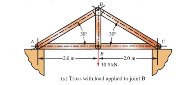
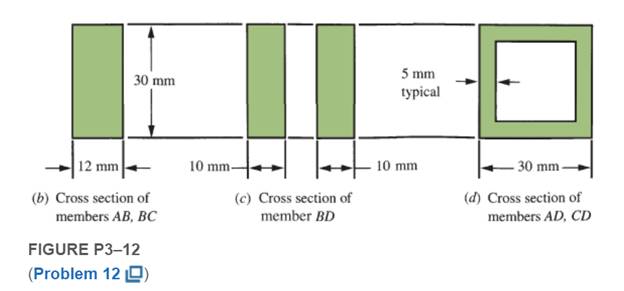
Figure P3−12 shows a small truss spanning between solid supports and suspending a 10.5 kN load. The cross sections for the three main types of truss members are shown. Compute the stresses in all of the members of the truss near their midpoints away from the connections. Consider all joints to be pinned.


Expert Solution & Answer
Want to see the full answer?
Check out a sample textbook solution
Students have asked these similar questions
Q11. Determine the magnitude of the reaction force at C.
1.5 m
a)
4 KN
D
b)
6.5 kN
c)
8 kN
d)
e)
11.3 KN
20 kN
-1.5 m-
C
4 kN
-1.5 m
B
Mechanical engineering, No
Chatgpt.
please help with this practice problem(not a graded assignment, this is a practice exam), and please explain how to use sohcahtoa
Solve this problem and show all of the work
Chapter 3 Solutions
Machine Elements in Mechanical Design (6th Edition) (What's New in Trades & Technology)
Ch. 3 - A tensile member in a machine structure is...Ch. 3 - Compute the stress in a round bar having a...Ch. 3 - Compute the stress in a rectangular bar having...Ch. 3 - A link in a packaging machine mechanism has a...Ch. 3 - Two circular rods support the 3800 lb weight of a...Ch. 3 - A tensile load of 5.00 kN is applied to a square...Ch. 3 - An aluminum rod is made in the form of a hollow...Ch. 3 - Compute the stress in the middle portion of rod AC...Ch. 3 - Compute the forces in the two angled rods in...Ch. 3 - If the rods from Problem 9 are circular, determine...
Ch. 3 - Repeat Problems 9 and 10 if the angle is 15 .Ch. 3 - Figure P312 shows a small truss spanning between...Ch. 3 - The truss shown in Figure P313 spans a total space...Ch. 3 - Figure P314 shows a short leg for a machine that...Ch. 3 - Consider the short compression member shown in...Ch. 3 - Refer Figure P38 . Each of the pins at A, B, and C...Ch. 3 - Compute the shear stress in the pins connecting...Ch. 3 - Prob. 18PCh. 3 - Prob. 19PCh. 3 - Prob. 20PCh. 3 - Prob. 21PCh. 3 - Compute the torsional shear stress in a circular...Ch. 3 - If the shaft of Problem 22 is 850 mm long and is...Ch. 3 - Compute the torsional shear stress due to a torque...Ch. 3 - Compute the torsional shear stress in a solid...Ch. 3 - Compute the torsional shear stress in a hollow...Ch. 3 - Compute the angle of twist for the hollow shaft of...Ch. 3 - A square steel bar, 25 mm on a side and 650 mm...Ch. 3 - A 3.00 in-diameter steel bar has a flat milled on...Ch. 3 - A commercial steel supplier lists rectangular...Ch. 3 - A beam is simply supported and carries the load...Ch. 3 - For each beam of Problem 31, compute its weight if...Ch. 3 - For each beam of Problem 31, compute the maximum...Ch. 3 - For the beam loading of Figure P334, draw the...Ch. 3 - For the beam loading of Figure P334, design the...Ch. 3 - Figure P336 shows a beam made from 4 in schedule...Ch. 3 - Select an aluminum I-beam shape to carry the load...Ch. 3 - Figure P338 represents a wood joist for a...Ch. 3 - For Problems 39 through 50, draw the free-body...Ch. 3 - Prob. 40PCh. 3 - For Problems 39 through 50, draw the free-body...Ch. 3 - Prob. 42PCh. 3 - Prob. 43PCh. 3 - Prob. 44PCh. 3 - For Problems 39 through 50, draw the free-body...Ch. 3 - For Problems 39 through 50, draw the free-body...Ch. 3 - For Problems 39 through 50, draw the free-body...Ch. 3 - For Problems 4850, draw the free-body diagram of...Ch. 3 - For Problems 4850, draw the free-body diagram of...Ch. 3 - Prob. 50PCh. 3 - Compute the maximum tensile stress in the bracket...Ch. 3 - Compute the maximum tensile and compressive...Ch. 3 - For the lever shown in Figure P353 (a), compute...Ch. 3 - Compute the maximum tensile stress at sections A...Ch. 3 - Prob. 55PCh. 3 - Refer to Figure P38. Compute the maximum tensile...Ch. 3 - Prob. 57PCh. 3 - Refer to P342. Compute the maximum stress in the...Ch. 3 - Refer to P343. Compute the maximum stress in the...Ch. 3 - Prob. 60PCh. 3 - Figure P361 shows a valve stem from an engine...Ch. 3 - The conveyor fixture shown in Figure P362 carries...Ch. 3 - For the flat plate in tension in Figure P363,...Ch. 3 - For Problems 64 through 68, compute the maximum...Ch. 3 - For Problems 64 through 68, compute the maximum...Ch. 3 - For Problems 64 through 68, compute the maximum...Ch. 3 - For Problems 64 through 68, compute the maximum...Ch. 3 - Prob. 68PCh. 3 - Figure P369 shows a horizontal beam supported by a...Ch. 3 - Prob. 70PCh. 3 - Prob. 71PCh. 3 - The beam shown in Figure P372 is a stepped, flat...Ch. 3 - Figure P373 shows a stepped, flat bar having a...Ch. 3 - Figure P374 shows a bracket carrying opposing...Ch. 3 - Prob. 75PCh. 3 - Figure P376 shows a lever made from a rectangular...Ch. 3 - For the lever in P376, determine the maximum...Ch. 3 - Figure P378 shows a shaft that is loaded only in...Ch. 3 - Prob. 79PCh. 3 - Prob. 80PCh. 3 - A hanger is made from ASTM A36 structural steel...Ch. 3 - A coping saw frame shown in Figure P382 is made...Ch. 3 - Prob. 83PCh. 3 - Figure P384 shows a hand garden tool used to break...Ch. 3 - Figure P385 shows a basketball backboard and goal...Ch. 3 - Prob. 86P
Knowledge Booster
Learn more about
Need a deep-dive on the concept behind this application? Look no further. Learn more about this topic, mechanical-engineering and related others by exploring similar questions and additional content below.Similar questions
- Solve this problem and show all of the workarrow_forwardaversity of Baoyion aculty of Engineering-AIMusyab Automobile Eng. Dep. Year: 2022-2023, st Course, 1st Attempt Stage: 3rd Subject: Heat Transfer I Date: 2023\01\23- Monday Time: 3 Hours Q4: A thick slab of copper initially at a uniform temperature of 20°C is suddenly exposed to radiation at one surface such that the net heat flux is maintained at a constant value of 3×10⁵ W/m². Using the explicit finite-difference techniques with a space increment of Ax = = 75 mm, determine the temperature at the irradiated surface and at an interior point that is 150 mm from the surface after 2 min have elapsed. Q5: (12.5 M) A) A steel bar 2.5 cm square and 7.5 cm long is initially at a temperature of 250°C. It is immersed in a tank of oil maintained at 30°C. The heat-transfer coefficient is 570 W/m². C. Calculate the temperature in the center of the bar after 3 min. B) Air at 90°C and atmospheric pressure flows over a horizontal flat plate at 60 m/s. The plate is 60 cm square and is maintained at a…arrow_forwardUniversity of Baby on Faculty of Engineering-AIMusyab Automobile Eng. Dep. Year: 2022-2023. 1 Course, 1" Attempt Stage 3 Subject Heat Transfer I Date: 2023 01 23- Monday Time: 3 Hours Notes: Q1: • • Answer four questions only Use Troles and Appendices A) A flat wall is exposed to an environmental temperature of 38°C. The wall is covered with a layer of insulation 2.5 cm thick whose thermal conductivity is 1.4 W/m. C, and the temperature of the wall on the inside of the insulation is 315°C. The wall loses heat to the environment by convection. Compute the value of the convection heat-transfer coefficient that must be maintained on the outer surface of the insulation to ensure that the outer-surface temperature does not exceed 41°C. B) A vertical square plate, 30 cm on a side, is maintained at 50°C and exposed to room air at 20°C. The surface emissivity is 0.8. Calculate the total heat lost by both sides of the plate. (12.5 M) Q2: An aluminum fin 1.5 mm thick is placed on a circular tube…arrow_forward
- Solve this and show all of the workarrow_forwardNeed helparrow_forwardY F1 α В X F2 You and your friends are planning to move the log. The log. needs to be moved straight in the x-axis direction and it takes a combined force of 2.9 kN. You (F1) are able to exert 610 N at a = 32°. What magnitude (F2) and direction (B) do you needs your friends to pull? Your friends had to pull at: magnitude in Newton, F2 = direction in degrees, ẞ = N degarrow_forward
arrow_back_ios
SEE MORE QUESTIONS
arrow_forward_ios
Recommended textbooks for you
 Mechanics of Materials (MindTap Course List)Mechanical EngineeringISBN:9781337093347Author:Barry J. Goodno, James M. GerePublisher:Cengage Learning

Mechanics of Materials (MindTap Course List)
Mechanical Engineering
ISBN:9781337093347
Author:Barry J. Goodno, James M. Gere
Publisher:Cengage Learning
Mechanical SPRING DESIGN Strategy and Restrictions in Under 15 Minutes!; Author: Less Boring Lectures;https://www.youtube.com/watch?v=dsWQrzfQt3s;License: Standard Youtube License