
Machine Elements in Mechanical Design (6th Edition) (What's New in Trades & Technology)
6th Edition
ISBN: 9780134441184
Author: Robert L. Mott, Edward M. Vavrek, Jyhwen Wang
Publisher: PEARSON
expand_more
expand_more
format_list_bulleted
Concept explainers
Videos
Textbook Question
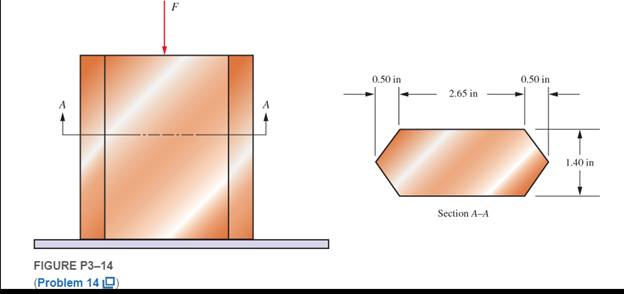
Chapter 3, Problem 14P
Figure P3−14 shows a short leg for a machine that carries a direct compression load. Compute the compressive stress if the cross section has the shape shown and the applied force is
Expert Solution & Answer
Want to see the full answer?
Check out a sample textbook solution
Students have asked these similar questions
Q11. Determine the magnitude of the reaction force at C.
1.5 m
a)
4 KN
D
b)
6.5 kN
c)
8 kN
d)
e)
11.3 KN
20 kN
-1.5 m-
C
4 kN
-1.5 m
B
Mechanical engineering, No
Chatgpt.
please help with this practice problem(not a graded assignment, this is a practice exam), and please explain how to use sohcahtoa
Solve this problem and show all of the work
Chapter 3 Solutions
Machine Elements in Mechanical Design (6th Edition) (What's New in Trades & Technology)
Ch. 3 - A tensile member in a machine structure is...Ch. 3 - Compute the stress in a round bar having a...Ch. 3 - Compute the stress in a rectangular bar having...Ch. 3 - A link in a packaging machine mechanism has a...Ch. 3 - Two circular rods support the 3800 lb weight of a...Ch. 3 - A tensile load of 5.00 kN is applied to a square...Ch. 3 - An aluminum rod is made in the form of a hollow...Ch. 3 - Compute the stress in the middle portion of rod AC...Ch. 3 - Compute the forces in the two angled rods in...Ch. 3 - If the rods from Problem 9 are circular, determine...
Ch. 3 - Repeat Problems 9 and 10 if the angle is 15 .Ch. 3 - Figure P312 shows a small truss spanning between...Ch. 3 - The truss shown in Figure P313 spans a total space...Ch. 3 - Figure P314 shows a short leg for a machine that...Ch. 3 - Consider the short compression member shown in...Ch. 3 - Refer Figure P38 . Each of the pins at A, B, and C...Ch. 3 - Compute the shear stress in the pins connecting...Ch. 3 - Prob. 18PCh. 3 - Prob. 19PCh. 3 - Prob. 20PCh. 3 - Prob. 21PCh. 3 - Compute the torsional shear stress in a circular...Ch. 3 - If the shaft of Problem 22 is 850 mm long and is...Ch. 3 - Compute the torsional shear stress due to a torque...Ch. 3 - Compute the torsional shear stress in a solid...Ch. 3 - Compute the torsional shear stress in a hollow...Ch. 3 - Compute the angle of twist for the hollow shaft of...Ch. 3 - A square steel bar, 25 mm on a side and 650 mm...Ch. 3 - A 3.00 in-diameter steel bar has a flat milled on...Ch. 3 - A commercial steel supplier lists rectangular...Ch. 3 - A beam is simply supported and carries the load...Ch. 3 - For each beam of Problem 31, compute its weight if...Ch. 3 - For each beam of Problem 31, compute the maximum...Ch. 3 - For the beam loading of Figure P334, draw the...Ch. 3 - For the beam loading of Figure P334, design the...Ch. 3 - Figure P336 shows a beam made from 4 in schedule...Ch. 3 - Select an aluminum I-beam shape to carry the load...Ch. 3 - Figure P338 represents a wood joist for a...Ch. 3 - For Problems 39 through 50, draw the free-body...Ch. 3 - Prob. 40PCh. 3 - For Problems 39 through 50, draw the free-body...Ch. 3 - Prob. 42PCh. 3 - Prob. 43PCh. 3 - Prob. 44PCh. 3 - For Problems 39 through 50, draw the free-body...Ch. 3 - For Problems 39 through 50, draw the free-body...Ch. 3 - For Problems 39 through 50, draw the free-body...Ch. 3 - For Problems 4850, draw the free-body diagram of...Ch. 3 - For Problems 4850, draw the free-body diagram of...Ch. 3 - Prob. 50PCh. 3 - Compute the maximum tensile stress in the bracket...Ch. 3 - Compute the maximum tensile and compressive...Ch. 3 - For the lever shown in Figure P353 (a), compute...Ch. 3 - Compute the maximum tensile stress at sections A...Ch. 3 - Prob. 55PCh. 3 - Refer to Figure P38. Compute the maximum tensile...Ch. 3 - Prob. 57PCh. 3 - Refer to P342. Compute the maximum stress in the...Ch. 3 - Refer to P343. Compute the maximum stress in the...Ch. 3 - Prob. 60PCh. 3 - Figure P361 shows a valve stem from an engine...Ch. 3 - The conveyor fixture shown in Figure P362 carries...Ch. 3 - For the flat plate in tension in Figure P363,...Ch. 3 - For Problems 64 through 68, compute the maximum...Ch. 3 - For Problems 64 through 68, compute the maximum...Ch. 3 - For Problems 64 through 68, compute the maximum...Ch. 3 - For Problems 64 through 68, compute the maximum...Ch. 3 - Prob. 68PCh. 3 - Figure P369 shows a horizontal beam supported by a...Ch. 3 - Prob. 70PCh. 3 - Prob. 71PCh. 3 - The beam shown in Figure P372 is a stepped, flat...Ch. 3 - Figure P373 shows a stepped, flat bar having a...Ch. 3 - Figure P374 shows a bracket carrying opposing...Ch. 3 - Prob. 75PCh. 3 - Figure P376 shows a lever made from a rectangular...Ch. 3 - For the lever in P376, determine the maximum...Ch. 3 - Figure P378 shows a shaft that is loaded only in...Ch. 3 - Prob. 79PCh. 3 - Prob. 80PCh. 3 - A hanger is made from ASTM A36 structural steel...Ch. 3 - A coping saw frame shown in Figure P382 is made...Ch. 3 - Prob. 83PCh. 3 - Figure P384 shows a hand garden tool used to break...Ch. 3 - Figure P385 shows a basketball backboard and goal...Ch. 3 - Prob. 86P
Knowledge Booster


Learn more about
Need a deep-dive on the concept behind this application? Look no further. Learn more about this topic, mechanical-engineering and related others by exploring similar questions and additional content below.Similar questions
- Solve this problem and show all of the workarrow_forwardaversity of Baoyion aculty of Engineering-AIMusyab Automobile Eng. Dep. Year: 2022-2023, st Course, 1st Attempt Stage: 3rd Subject: Heat Transfer I Date: 2023\01\23- Monday Time: 3 Hours Q4: A thick slab of copper initially at a uniform temperature of 20°C is suddenly exposed to radiation at one surface such that the net heat flux is maintained at a constant value of 3×10⁵ W/m². Using the explicit finite-difference techniques with a space increment of Ax = = 75 mm, determine the temperature at the irradiated surface and at an interior point that is 150 mm from the surface after 2 min have elapsed. Q5: (12.5 M) A) A steel bar 2.5 cm square and 7.5 cm long is initially at a temperature of 250°C. It is immersed in a tank of oil maintained at 30°C. The heat-transfer coefficient is 570 W/m². C. Calculate the temperature in the center of the bar after 3 min. B) Air at 90°C and atmospheric pressure flows over a horizontal flat plate at 60 m/s. The plate is 60 cm square and is maintained at a…arrow_forwardUniversity of Baby on Faculty of Engineering-AIMusyab Automobile Eng. Dep. Year: 2022-2023. 1 Course, 1" Attempt Stage 3 Subject Heat Transfer I Date: 2023 01 23- Monday Time: 3 Hours Notes: Q1: • • Answer four questions only Use Troles and Appendices A) A flat wall is exposed to an environmental temperature of 38°C. The wall is covered with a layer of insulation 2.5 cm thick whose thermal conductivity is 1.4 W/m. C, and the temperature of the wall on the inside of the insulation is 315°C. The wall loses heat to the environment by convection. Compute the value of the convection heat-transfer coefficient that must be maintained on the outer surface of the insulation to ensure that the outer-surface temperature does not exceed 41°C. B) A vertical square plate, 30 cm on a side, is maintained at 50°C and exposed to room air at 20°C. The surface emissivity is 0.8. Calculate the total heat lost by both sides of the plate. (12.5 M) Q2: An aluminum fin 1.5 mm thick is placed on a circular tube…arrow_forward
- Solve this and show all of the workarrow_forwardNeed helparrow_forwardY F1 α В X F2 You and your friends are planning to move the log. The log. needs to be moved straight in the x-axis direction and it takes a combined force of 2.9 kN. You (F1) are able to exert 610 N at a = 32°. What magnitude (F2) and direction (B) do you needs your friends to pull? Your friends had to pull at: magnitude in Newton, F2 = direction in degrees, ẞ = N degarrow_forward
arrow_back_ios
SEE MORE QUESTIONS
arrow_forward_ios
Recommended textbooks for you
 Mechanics of Materials (MindTap Course List)Mechanical EngineeringISBN:9781337093347Author:Barry J. Goodno, James M. GerePublisher:Cengage Learning
Mechanics of Materials (MindTap Course List)
Mechanical Engineering
ISBN:9781337093347
Author:Barry J. Goodno, James M. Gere
Publisher:Cengage Learning
Understanding Shear Force and Bending Moment Diagrams; Author: The Efficient Engineer;https://www.youtube.com/watch?v=C-FEVzI8oe8;License: Standard YouTube License, CC-BY
Bending Stress; Author: moodlemech;https://www.youtube.com/watch?v=9QIqewkE6xM;License: Standard Youtube License